Monthly Archives: April 2018

Firepit rolling base

A quick little project that I knocked out in a couple of hours today…

My wife an I own a Solo Stove Bonfire. And yes, it does work every bit as well as they say.

The problem is the somewhat fickle Seattle weather; we might have a fire and then the firepit would sit outside and get rained on. It’s stainless so it’s supposed to not corrode, but there are a still a few issues. The obvious thing is to put it under cover when you are done, but it’s really really hot and I’m quite lazy.

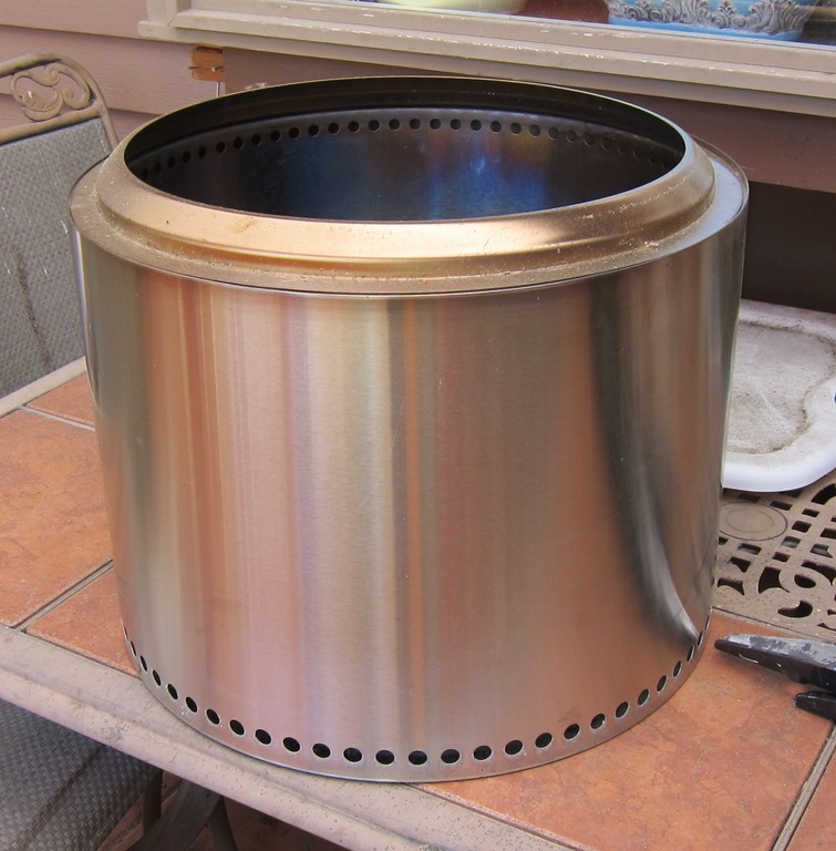
A few days ago, I came up with a plan. I will start with the Solo Stove:

IMG_9202

My original plan was to buy some angle iron to make a frame, but walking around I found an alternative material:

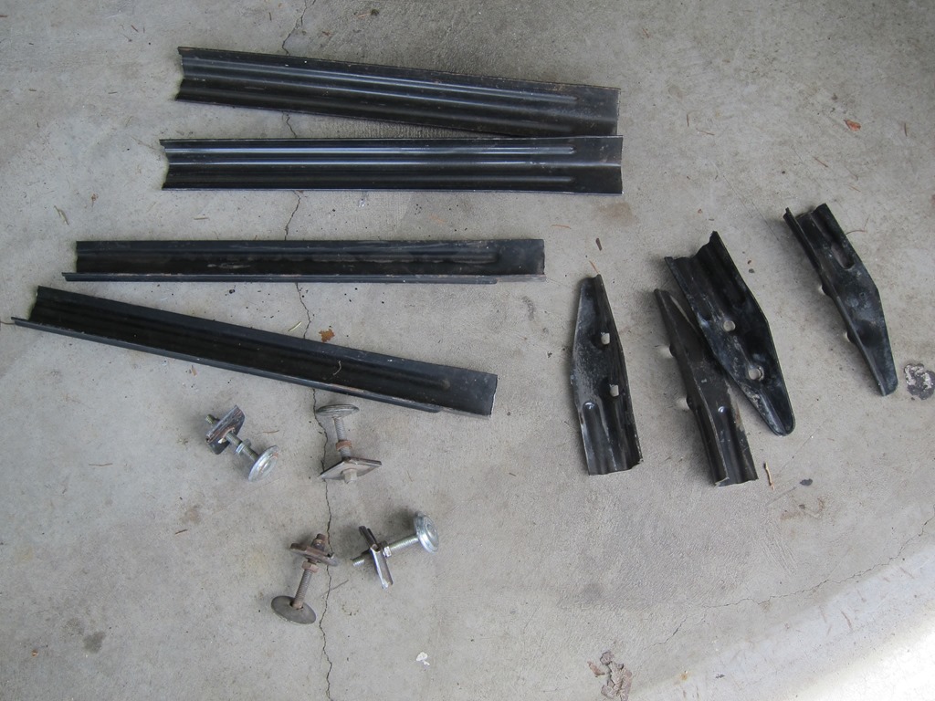
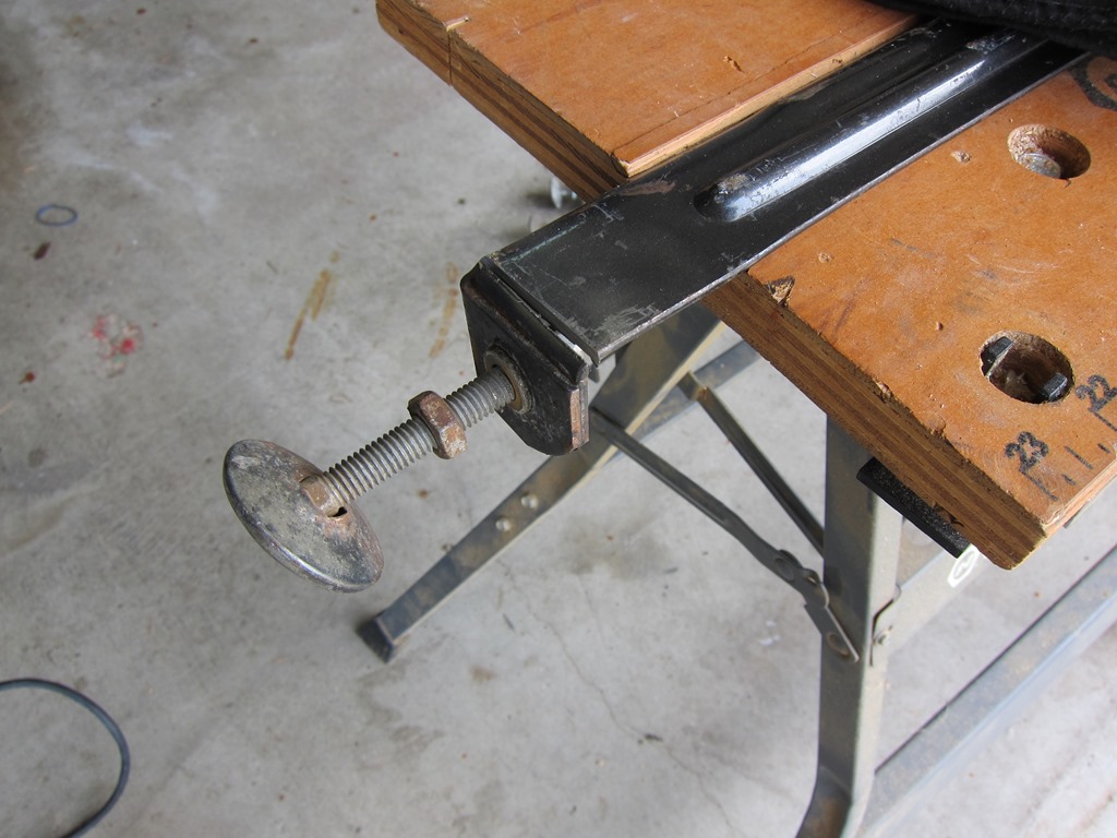
Four pinball legs that I got with the World Cup Soccer ‘94 that I bought last fall, since replaced with pretty new ones. These legs were just waiting to head to the dump.

IMG_9203

and four leftover casters from my Glowforge table project. I didn’t take a picture of them.

Leg modifications

The legs need to be converted from their current form into something more like angle iron. The first step is to cut off the feet. Out comes the 4” angle grinder, on goes the accessory handle and a 4” metal cutting disk, and the feet are cut off.

IMG_9204

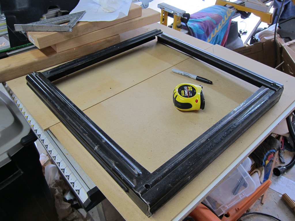
The process is repeated at the other end to cut off the mounting holes. The length is based upon the diameter of the solo stove, which is 19.25”. After a few minutes of cutting and a lot of sparks, we end up with the following:

IMG_9205

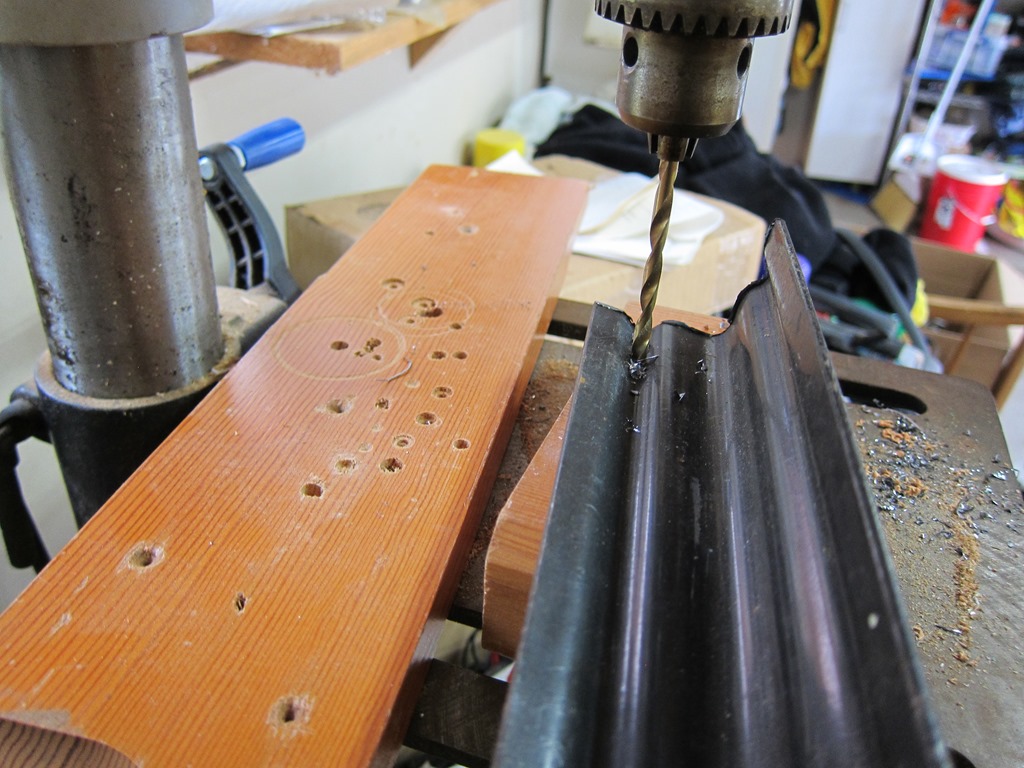
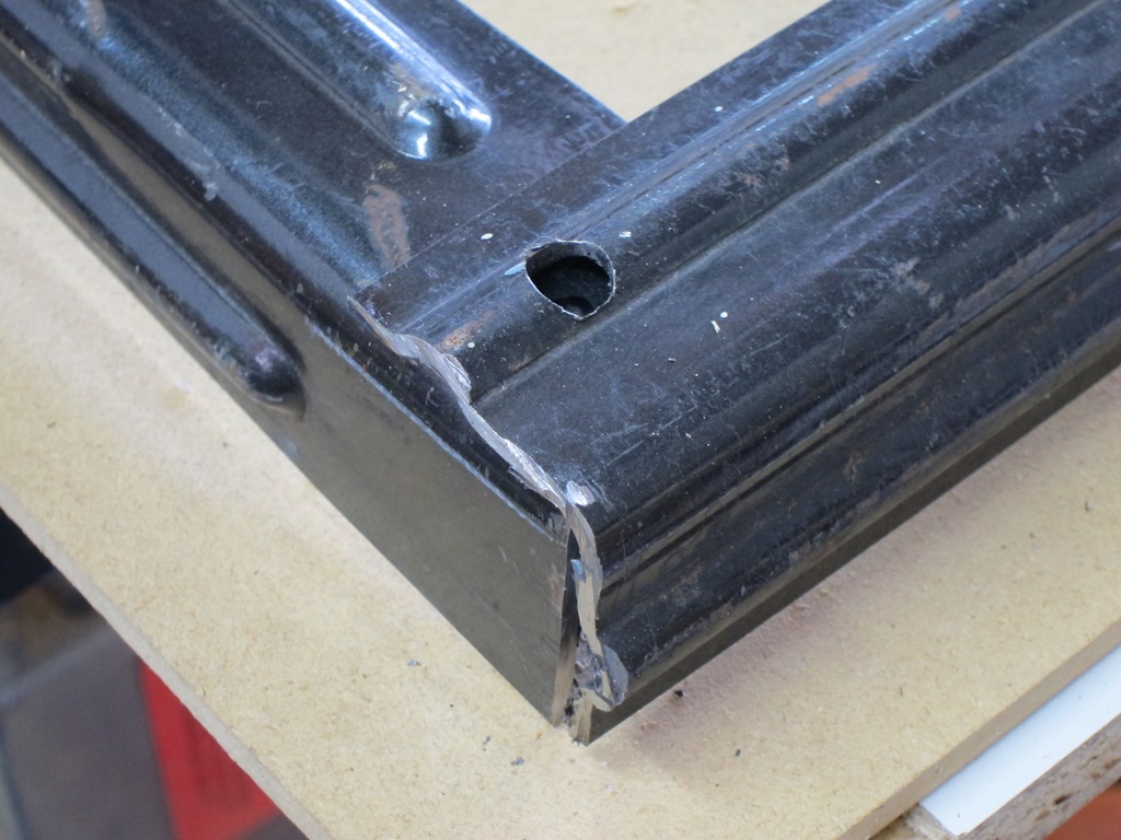
Next, I need mounting holes in the corner that the casters can go through. The fluted design of the legs made this a significant pain in the ass, even with a drill press. Here’s the first hole drilled with a 1/8” bit IIRC; I would enlarge it with a 2/8” bit on the way to a 3/8” bit. The drill press is a huge help in this sort of work.

IMG_9206

Next it is time to do the layout so I can mark the holes where the metal pieces will overlap and connect:

IMG_9207

This is really not precision work, though I will note that I realigned this corner because the two pieces should be symmetrical:

IMG_9208

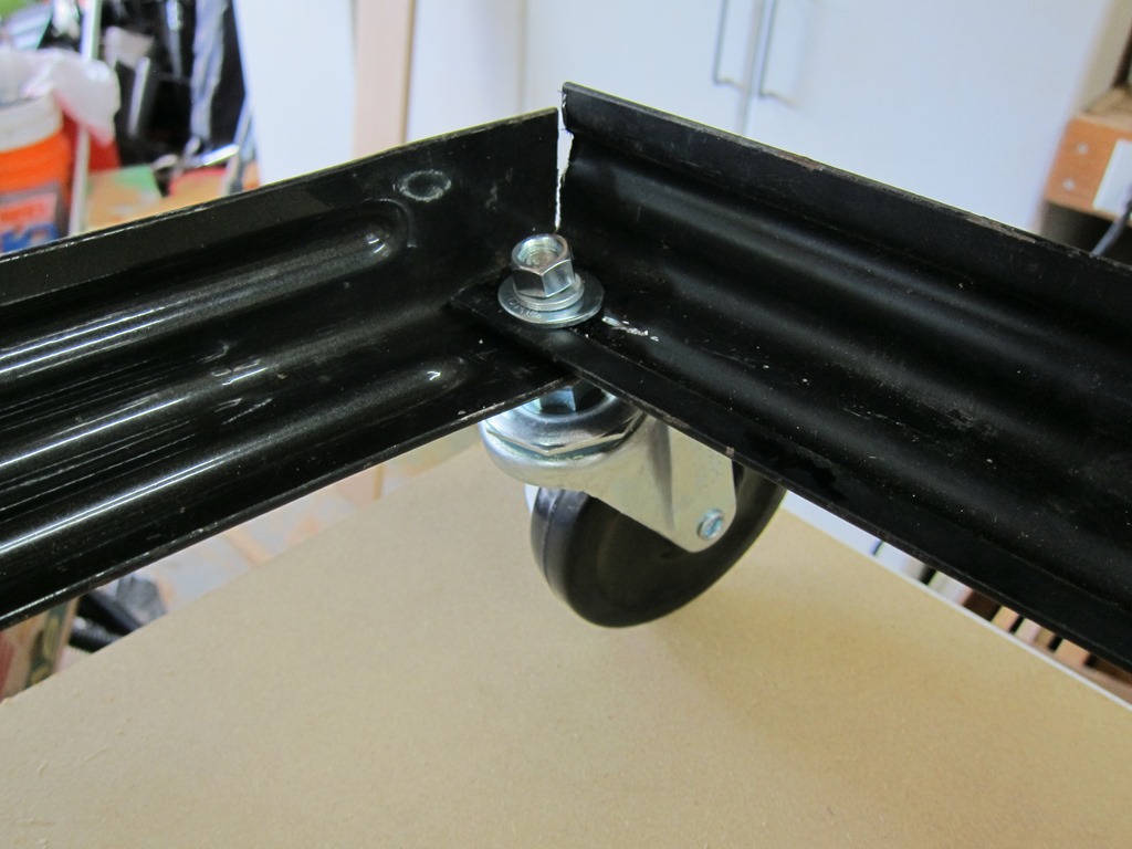
Then, it was back to drill 12 more holes (three pass x four pieces), and then it was time for assembly, in which our caters finally make an appearance:

IMG_9209

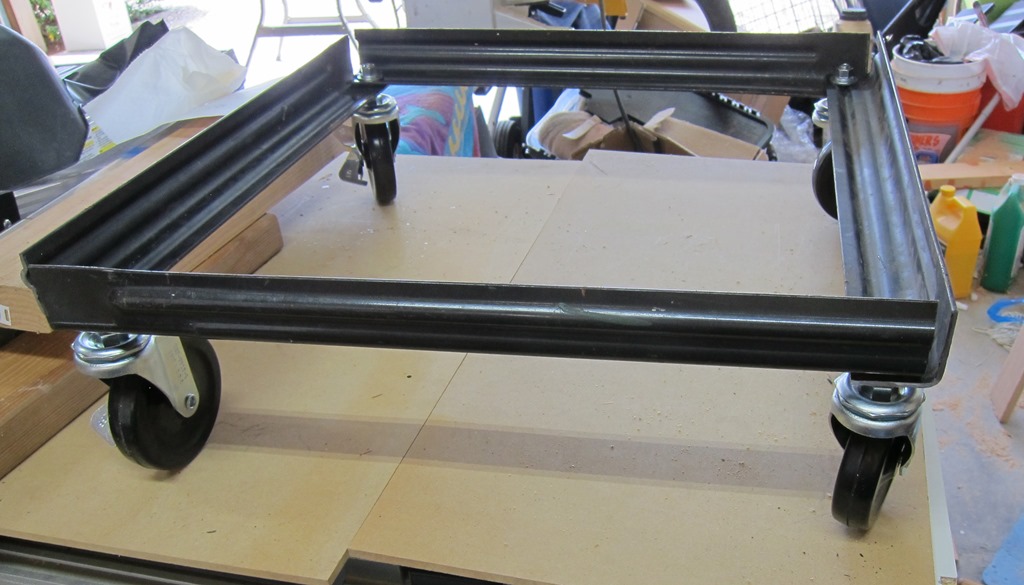
Tighten up all of the nuts, and we have a frame:

IMG_9210

I had toyed with the idea of painting a stainless steel color, but I’m cheap and lazy, so it’s like this for now.

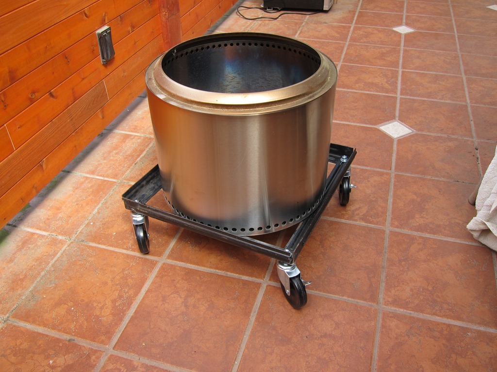
Beauty shot of the Solo Stove sitting in its new frame:

IMG_9211

Total cost was $2.09 for a new metal cutting blade and about $2.00 for 8 nuts, 4 flat washers, and 4 lockwashers.


An inexpensive glowforge stand…

My glowforge lives in a workshop I have that I’ve been working on fixing up. The workshop was bare studs but now it has plywood walls and some improved electrical.

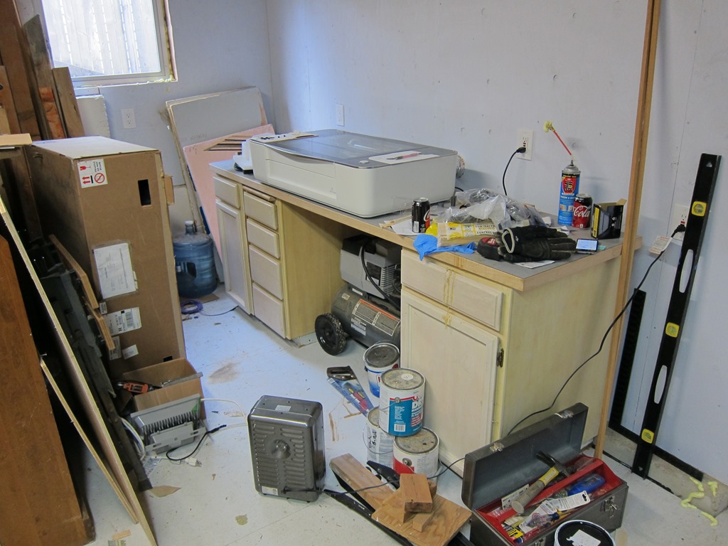
IMG_9196

As you can see, it’s sitting on top of some old and tired cabinets that I don’t use for storage because they don’t work very well, and a counter that sags in the middle. I need something to be better at holding both the glowforge and the other stuff I want to do down here (in particular, I need a place I can put a reflow oven for some electronics projects).

My initial thought was to price out some replacement cabinets and a countertop, but that quickly started looking like $800 – $1000 for the cheap stuff. So, what other alternatives could I use?

I was inspired by Mike’s table in this forum post:

That’s just a cheap home depot storage rack, only using part of it. I found a rack that was like it at Home Depot, and it was only $60:

But… It was only four feet wide, and I wanted some space to put my laptop and other stuff next to the glowforge. So, I started looking for racks that were wider but still 24” deep. The ones I found were a lot pricier; something like $150 or so.

Time passed, and I ended up on Costco’s website, and decided to search there.

1

What have we here? 60” wide, 24” deep, and a full 72” tall. $170, so not super cheap, but pretty close to what I wanted. I could put four shelves at the bottom for flat goods, and then one shelf at the top, and the glowforge would be at waist height. And wheels if I wanted them.

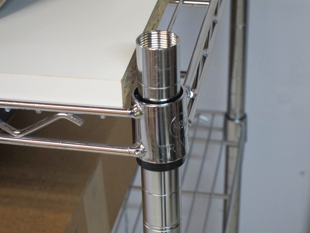
It took about a week to ship, and the box it showed up in was heavy. 104 pounds heavy. I dragged it off the front porch and into the garage, opened it up, and found that it was just what I expected. 5 shelves, and – to save on shipping costs – the corner posts come as two sections that screw together. I did some measurements, and realized that if I didn’t use the casters (it comes with both casters and normal feet), the length of he bottom posts was almost exactly counter height, which meant I could do a build that was pretty much at counter height.

And… if I only used 3 shelves on that, I could use the remaining parts – the upper posts and other two shelves – and build a second countertop-height system to go next to the first:

IMG_9197

So, that $170 got me two counters – one to hold the glowforge, and one to hold whatever else I want to put next to it. But if you didn’t want the second counter unit, you could easily put the other two shelves on the glowforge part and get a lot of storage for flat materials. And have it on wheels if that is useful for you.

There was only one problem. Wire shelves aren’t the nicest things to put stuff on as small items fall through the openings, and you can’t write on them either. What I needed was a countertop to go on top. There are a few options:

  • Buy one of the ikea countertops – like this or this – and trim them down. I would need two in this case, and that would be another $120. Decent idea, and I like the black look. So yes for fancy, but no for this setting.
  • Buy a full sheet of melamine. My lumberyard will sell me a 48” x 96” sheet for $35, and that would do both counters with some left over. Downside is that the 1/2” sheets are about 65 pounds and a bit of a pain to transport. And the exposed edges aren’t white.
  • Buy some pre-drilled shelf panels. These are meant to be used for the sides of cabinets with shelves in them. $38 each, and I would need two of them.

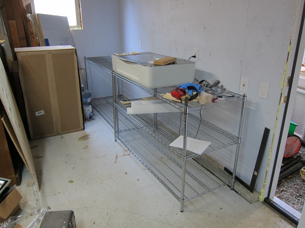
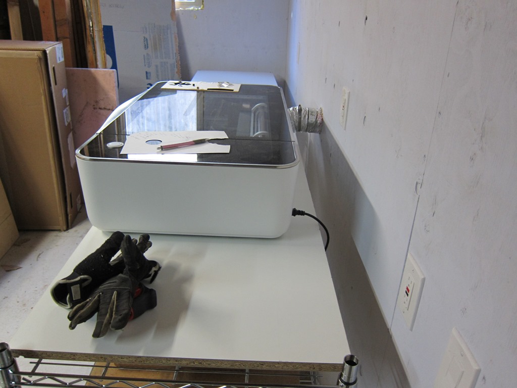
I was going to go with the big sheet for $35, but then I got to looking around and remembered that we had some extra Ikea shelves hanging around. They are about 29” x 24“, so I’ll just need to trim a bit off of them to make them the right depth (if they are trimmed to 23.5” they will fit between the front and back wire sections and not slide around). When I went and did that, I found that two of the shelves are almost perfect in length between the posts, and everything looks quite tidy. Here it is.

IMG_9199

Plenty of space for a laptop on the right side, lots of storage for stock underneath. I might build some vertical storage on the left side; not sure yet.

IMG_9200

The shelf is plenty deep; I have mine towards the front to make the exhaust fit better. What I really need to do is trim a couple inches off the duct.

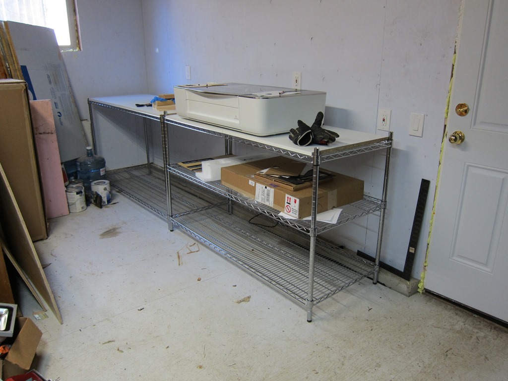
If you are going two countertop-high units, you’ll want to drop the first one down one inch so that everything is level. It looks like this.

IMG_9201


Building the Globe of Fire (Dodecahedral Light Engine)…

This guide will describe how to build the Globe of fire. You will need the right tools and good soldering skills to build it successfully.

Please read through the entire guide before you start assembly.

The kit comes with the following parts:

image

  • 12 polygonal face circuit boards, each with 3 WS2812 LEDs already mounted (you will only use 11 of these)
  • 1 bottom face with a big hole in it
  • Connecting wire that will be used to connect power and a control signal to the globe.
  • 4 assembly jibs to hold the polygonal faces at the proper angle
  • 1 1/4″ bolt and nut to serve as a base
  • 1 stand to hold the completed globe up
  • Approximately 60 tiny half-circle wires, used to connect the polygonal faces together.

11 pentagonal faces with WS2812 (aka “neopixel”) LEDs already soldered on. There is an additional face without LEDs with a hole for mounting the DLE.

To build the kit, you will need the following tools:
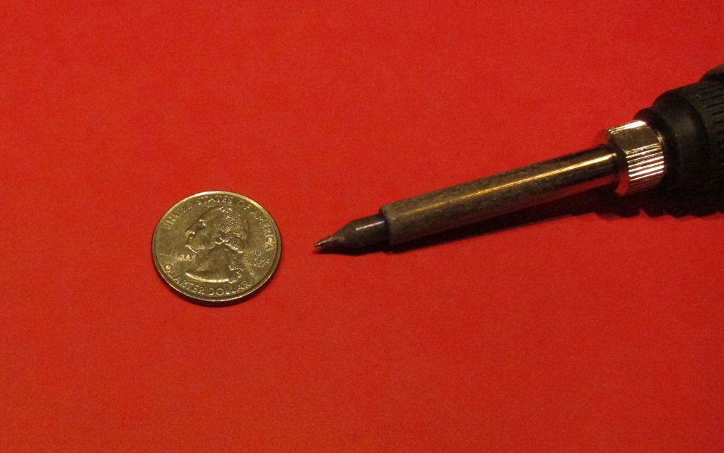
IMG_9080

A good soldering iron with a fine tip.
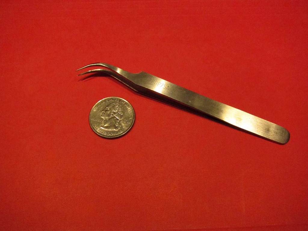
IMG_9081

Fine tipped tweezers.

IMG_9111

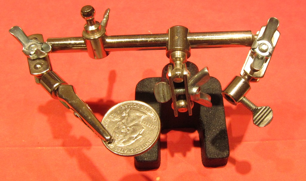
A third hand. Assembly will be very hard if you can’t hold the pieces in places while soldering.
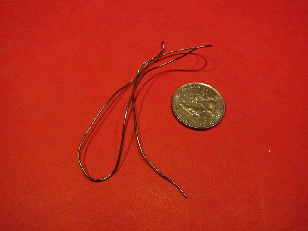
IMG_9084

Solder

Assembly

The globe consists of two rings composed of 5 faces each plus a top and a bottom. We will be joining together the power (VCC) and ground connections so that the LEDs all get power and ground. In addition, we will be connecting the data output from one face (DOUT) to the data input of one adjacent face so that the signals will travel correctly to all of the faces.

It will likely take a couple of hours of soldering to complete the assembly.

If you would like a refresher on how WS2812 LEDs work, there’s a good discussion on StackExchange here.

Building a ring

The tiny half-circle wires are very tiny and easily lost. Put them in something to keep them together. If you lose some, they are made out of 22 gauge solid copper wire.

Five of the pentagonal faces are used to build a ring.
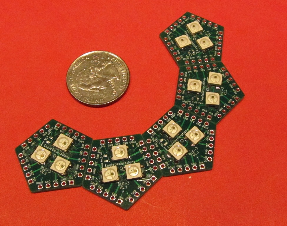
IMG_9087

Every face of the pentagon has identical connections so the orientation of an individual face is not important.

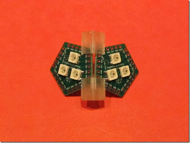
The alignment clamps are used to hold the boards together at the correct angle (116 degrees):
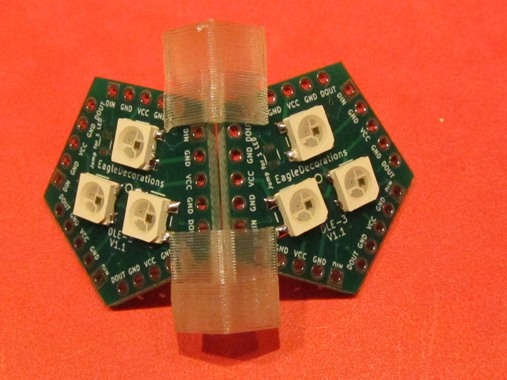
IMG_9089

Note that the two boards are parallel and there is only a small space between them. Also note that the left and right boards are aligned horizontally; the two VCC holes are aligned with each other.

Here are two wrong ways to do it:
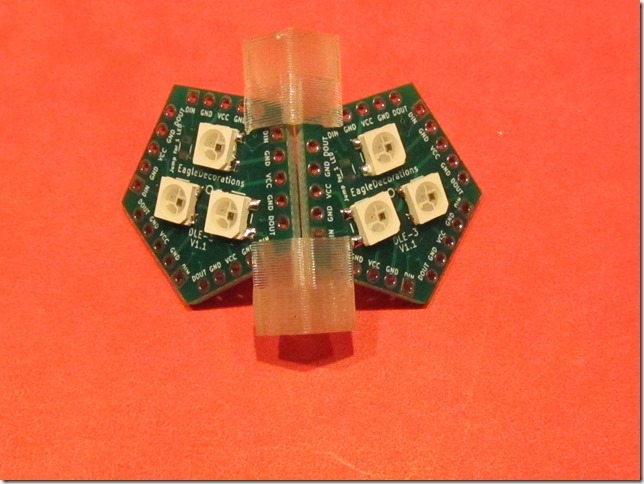
IMG_9090IMG_9091

In the left one, the two boards are misaligned vertically; the two VCC holes are not aligned horizontally. In the right one, the boards edges are not parallel.

The board alignment doesn’t have to be perfect, but it helps to have them pretty close.

In some orientations, the alignment clamps may contact the LEDs. If this happens, don’t push that clamp on fully; it will still work if near the edge of the board:

image

For the faces in the ring, we will connect both VCC and GND, and then we will connect the data output from the left face (DOUT) to the data input (DIN) on the right face. We will start with VCC.
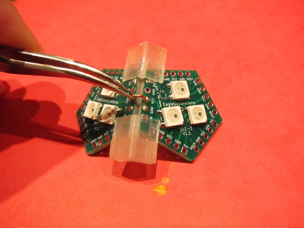
IMG_9093

We will be using a connection wire to make the connection. I have tried a few different ways of doing this, and the following is what I recommend:

  1. Add solder to the hole on one side of the connection (the right side in these pictures). Add enough so that there is a ball of solder protruding above the board.
  2. Hold the connecting wire in the middle and place one end of the wire in the hole without solder, and hold the other end against the hole with solder in it.
  3. Touch the soldering iron against the end with solder and lightly press the wire into the solder. It will melt and the wire will sink into the solder. Remove the iron, and hold the wire in position until the solder solidifies.
  4. Solder the other end normally. It works best if you get the solder in position and only apply the soldering iron only long enough to melt the solder. If you apply it too long, you will melt the other end and may have to resolder both.
  5. Verify that both solder joints are shiny and have enough solder. If the joints aren’t shiny, heat one at a time until it just goes liquid.

It’s going to take a little time to get the hang of this. Don’t worry, you will get faster.

After the VCC is connected, connect one of the GNDs to one of the others. It doesn’t matter which one you choose.

After VCC and GND are soldered, remove the assembly jigs so that you can solder DIN and DOUT. This will carry the data signal from the DOUT face into the DIN face.
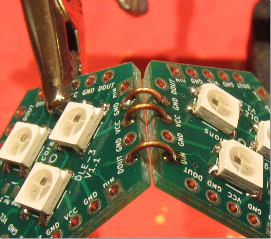
IMG_9114

In this detail, the right side (DIN) has been soldered, and left side is in the DOUT hole. The next step is to solder the DOUT end.

If the second end takes too long to solder, it may heat up the first end and the connecting wire may come loose. If that happens, just hold the wire to one end and heat it and wait for the heat to conduct down to the other end and melt the solder there.

That’s one face connected. There are a lot more, but it will get easier with practice.

We next add a third face using the same approach. It looks like this:
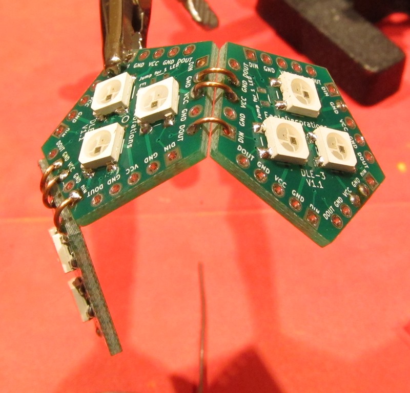
IMG_9110

Once we have three faces, assemble two more faces together. We will assemble the three and two face pieces to make a full ring. 

Make the ring
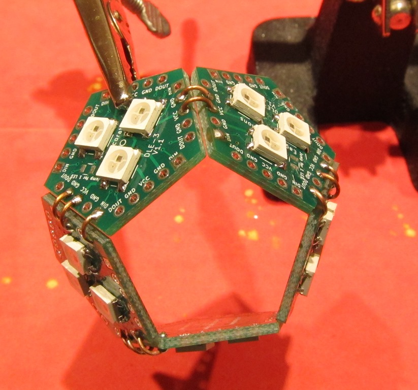
IMG_9112

Use the alignment clamps to hook the three-face section to the two-face section, and solder one set of connections between the two section and three section.

image

The last set of connections is different. Note that only the GND and VCC parts are connected; the data lines are unconnected. This is so that data can come into the ring and go out of it.

Looking at the input face, we notice that there is a connection to DOUT but not to DIN; for this face, the data will come in from a face that is not on this ring and then head out the left side of the face.

Looking at the output face, we notice that there is a connection to DIN for the data that has travelled around the ring, but no connection to DOUT. The data coming into the right face will head out of the ring to another face, either the top or a ring that will be attached below.

Adding the top
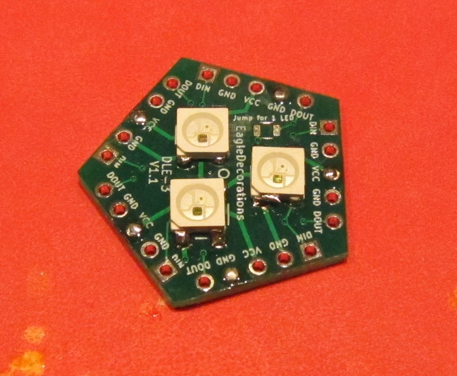
IMG_9102

We need to add wires to the top so it doesn’t fall through the middle of the ring, and each side will connect either VCC or GND. Start by adding solder to three VCC faces and two GND faces (one arrangement is shown above, but it doesn’t have to look exactly like this).

We need to prepare one connector on each side of the board with solder; either GND or VCC. Do three faces with VCC and two with GND.
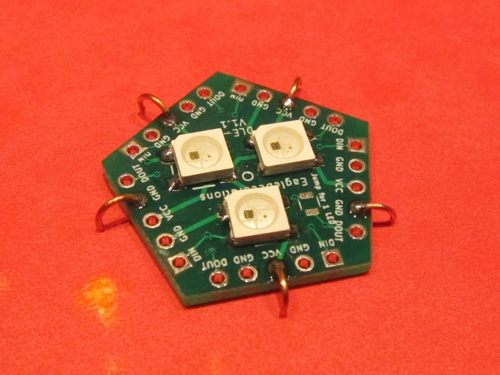
IMG_9103

To keep the top face from falling through, we need to put connections on it ahead of time. Note that each of these touches the surface; that will give us roughly the angle we need.
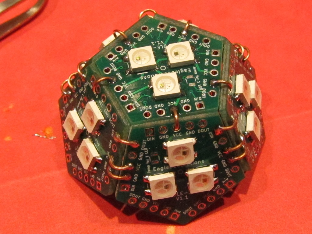
IMG_9104

The top face is just sitting there. Check that all the connections align properly with the connections from the ring. Solder all the VCC and GND connections to the ring. You may need to heat the already soldered wires to get them to align correctly with the holes on the ring.
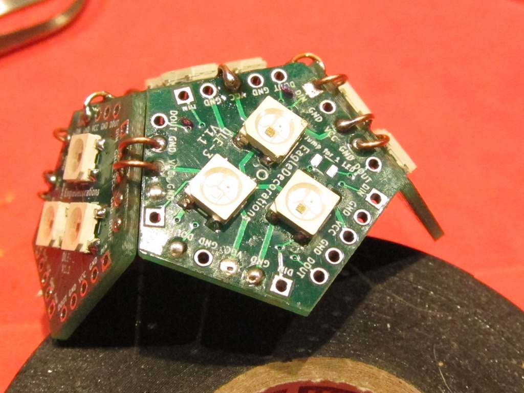
IMG_9105

Next, we need to make the data connection from the ring to the top. Find the face on the ring that does not have a connection to DOUT (the output face in the previous picture), and make a connection from the DOUT on that face to the DIN connection on the top face.

image

Finally, we find that face that has a DOUT connection but no DIN connections. This is the face that will connect across to the other ring. I have marked the two DIN connections with marker so we can find them later; ONE of these will be connected to the other ring.

If you have a controller than can drive these LEDs, it’s a good idea to test what you have built so far. Connect VCC to 5 volts, GND to ground, and DIN to your microcontroller, and run a program that can drive 33 LEDs. They should all light up. If they don’t, examine your solder connections and make sure that you don’t have DOUT/DIN connected all the way around the ring.

Building the second ring

The second ring is built using the same method as the first one. Do not add a top piece. 

image

This is the bottom ring and is actually upside down at this point. Eventually, we will need to make power, ground, and data connections for the whole globe. They are marked in blue on this face. Why did we choose this face? It’s the only one on the ring that has a DOUT connection but no DIN connection.

It’s a good idea to test this ring at this time.

image

This is the output face of the second ring. I have put marks on the two DOUT connections; one of them will hook up to the input face on the other ring.

image

Put the first ring and the second one together, making sure to align the rings so the face that has DOUT marked on the bottom ring is aligned with the DIN that is marked on the upper ring. Tape the two rings together. Connect those two pins together, then attach the top and bottom by connect VCC between three faces and GND between the other two.

At this point, the LED part of the globe is complete. Hook it up to your controller and verify that all of the faces light up. It should look like this (hand not included):
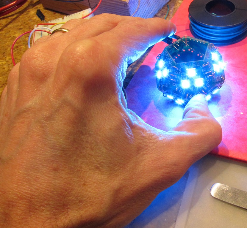
IMG_9120

Attaching the base

The base is purely used for mechanical support; the connections that are made do not carry electricity.
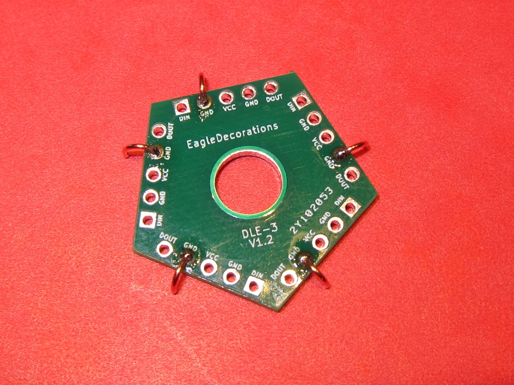
IMG_9162

We will use the special bottom pentagon; it has a hole in the middle and no other connections. Attach 5 wires to it on the GND connections, and make sure that you use a variety of GND connections.
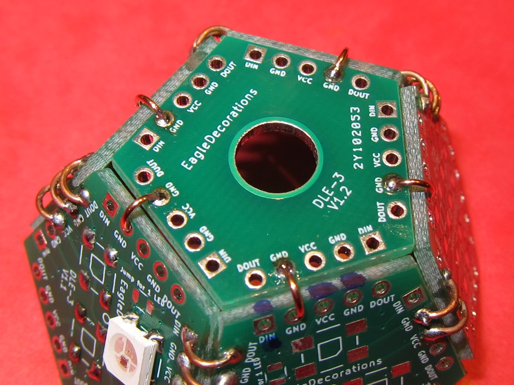
IMG_9163

Find the spot on the bottom ring where you will attach the wires – you should have marked it before. Rotate the bottom until one of the grounds lines up with the gap between the grounds on the wire-attachment face, as shown in the above picture.

Do not solder the bottom on yet.
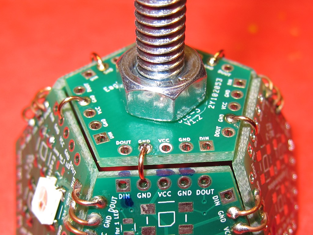
IMG_9164

Take the 1/4 screw and put in through the bottom face from the backside, and then put a nut on the outside face. You will want to tighten this out pretty well so that it doesn’t come loose.

And then solder the wires to hold the bottom on.
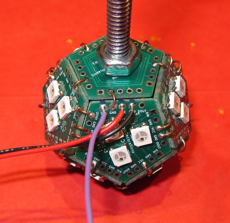
IMG_9165

Next, solder on the wires; red to VCC, black to GND, and purple to VIN.
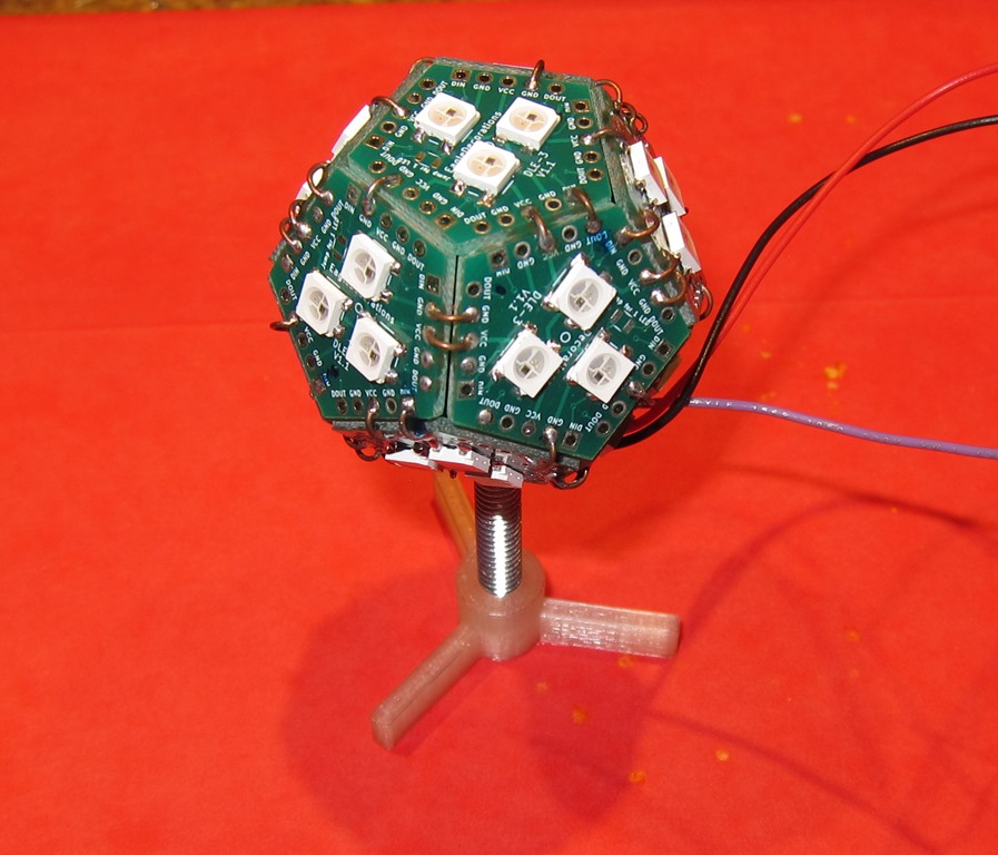
IMG_9166

Finally, screw the base onto the 1/4 bolt, and you’re done.

Hook it up, and it should look something like this:

IMG_9168

If you’d like a more diffused look, you can put an acrylic plastic globe over it

IMG_9170

Both of these pictures are with full lights on and with the globe powered by an underpowered USB source.


Finishing touches–USB charging station part 4

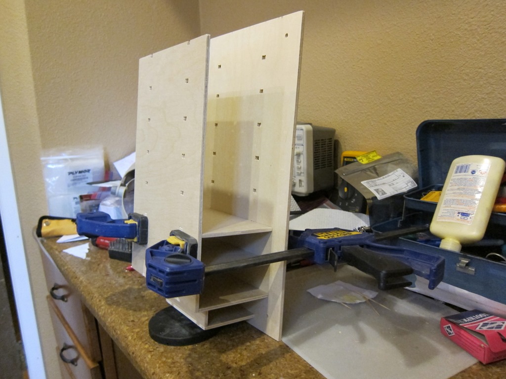
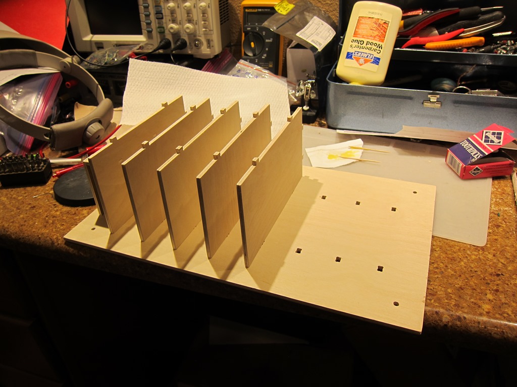
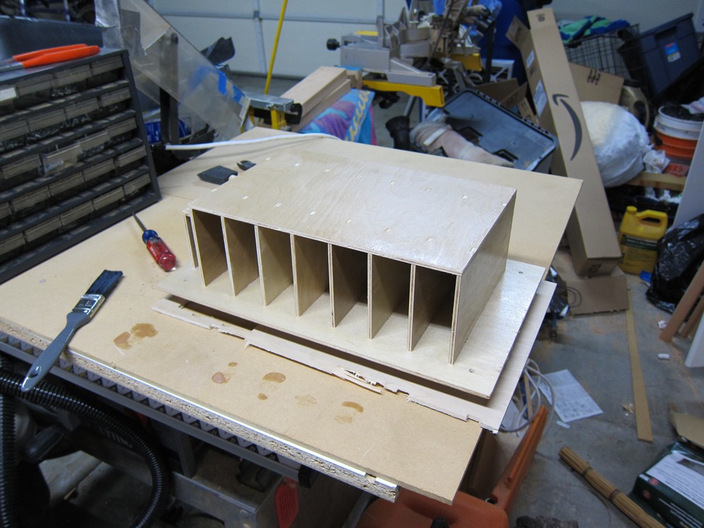
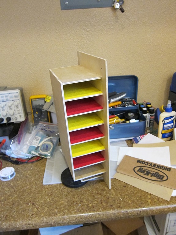
I spent a bit of time tuning all of the joints, cleaning out the dog bones so that they would look nice, and doing an overall sanding of all the plywood. Then it was on to gluing. This was done in sections so that it could be easily clamped together:

IMG_9186

IMG_9187

The top and back had to be glued all at once, and then clamped. I used a lot of clamps

Finishing was next. I decided to use a water-based polyurethane that I already had:

IMG_9188

If you look closely, you will see the base hovering above the platform. I build a little stand using the incorrect base piece I built earlier and some standoffs made of machine screws and nuts. That way, I could finish the bottom, flip it over, and finish the parts of the top that were not done. Finishing the inside of the cubbies was a significant pain in the butt.

After the finish dried, I sanded down the raised grain that water-based poly gives you and then put on… well, I was going to put on a second coat and then realized that I didn’t need the protection, so I called the finishing done.

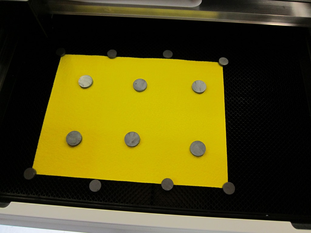
I wanted to have some padding for the cubbies to help hold the devices in, so I bought some felt at the fabric store. The pieces needed to be cut into simple rectangles – which would have been pretty easy to do with an x-acto knife, but when you have a laser cutter hanging out under the garage, there’s an easier way.

IMG_9189

Felt is pretty light and the laser cutter has air assist to clear away the smoke from the cutting, so you need to hold it down. The magnets are carefully aligned so they don’t overlap any of the cuts.

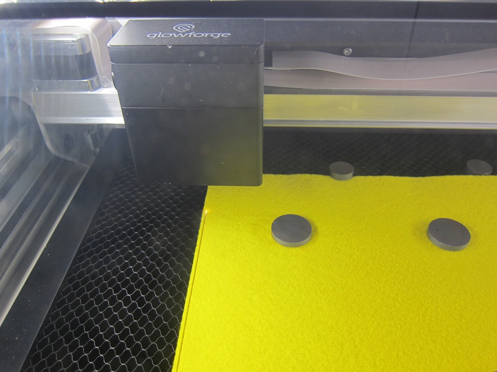
IMG_9190

An action shot of the cut.

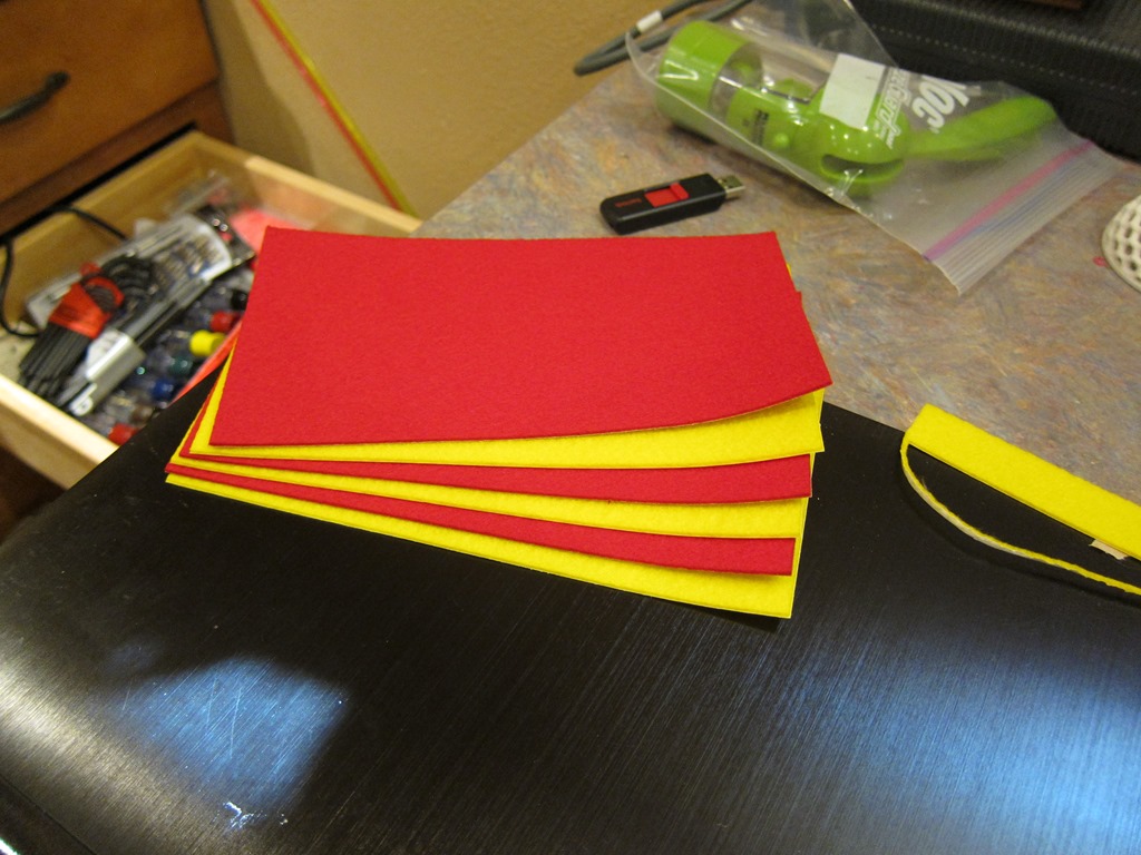
IMG_9192

And the result. Somewhat surprising to me, there was absolutely no charring at all on the felt; it looks like it was just cut with a very accurate knife.

IMG_9194

And here we are with the felt installed. There is no felt in the bottom since that part is just a pass-through for the cables (yes, it could have been more elegant). Putting the felt in was *interesting*. I’d peel of the backing, put it adhesive-side up on the appropriately-sized piece of cardboard from a Digi-Key box, and then, with the unit upside down, carefully lift it up to align the felt with the edge, and then press it down. It worked pretty well.

IMG_9195

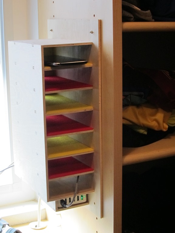
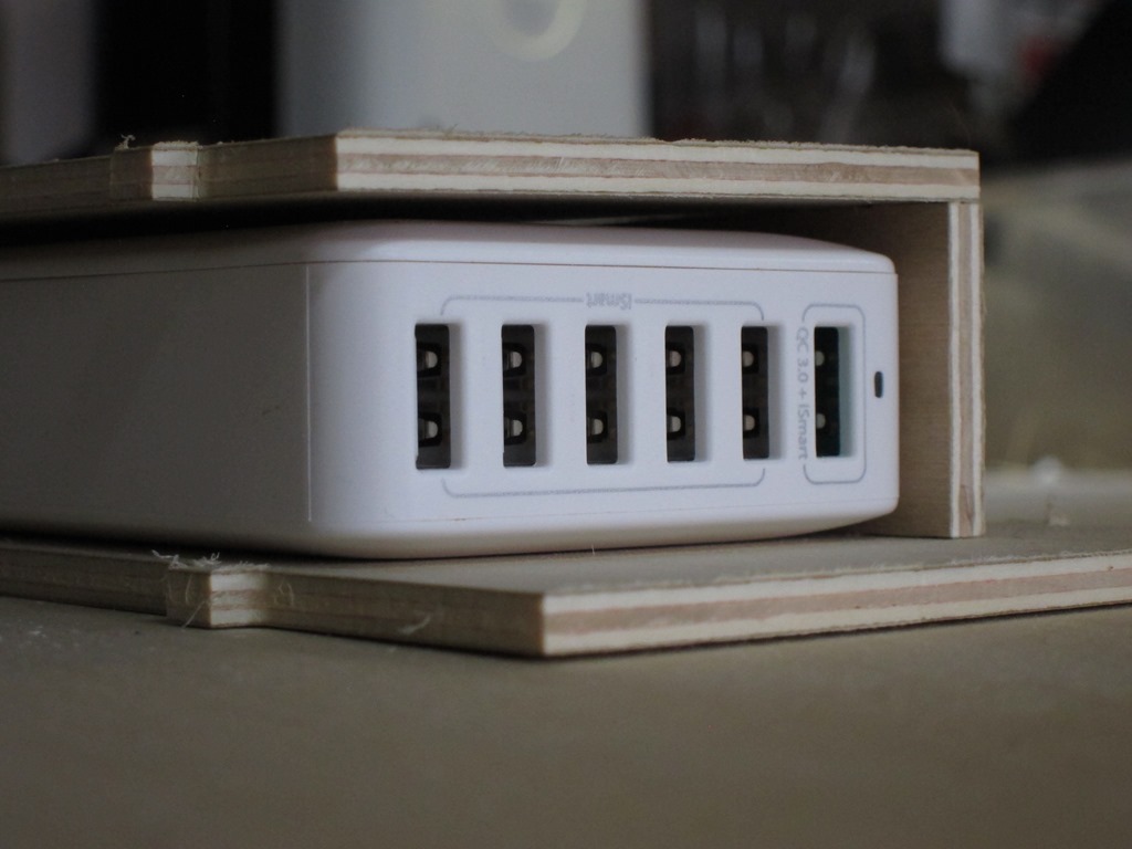
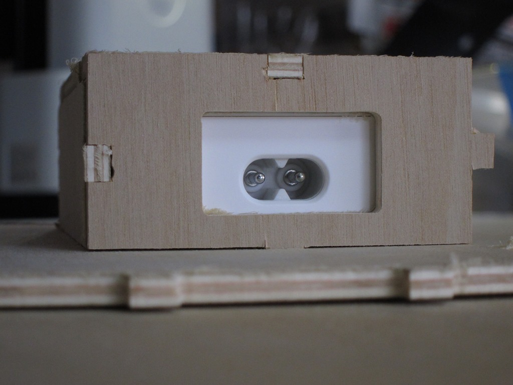
And finally, it was time for installation. The first shelf peg fit perfectly, the second one was offset by a bit, which means my measurements were off a bit. I enlarged the holes and it was fine. The bottom holes… well, they were off by about 1/4 inch. Which is a bit embarrassing. I did a bit of modification to two of the shelf pins with a grinding wheel in my Dremel to make the cylindrical part a bit longer so they would stick farther into the shelve, drilled a hole through the shelf below to add a grommet, and installed the hub. Here you see it charging my cell phone. I bought some more cables to use but they’re currently all in use for another project, so that’s why there is only one device.

Overall, I’m pretty happy about it; the project looks decent (if you like through-tab designs; I could have done a hidden tab design but chose not to for my first project) and I learned a lot about how to do the design and how to use the Shaper Origin.


A few cutting remarks–USB charging station part 3

In our previous episode, we had just finished cutting the hub portion of the station.

Now, it’s time to cut the remaining parts. I started by cutting the biggest part – the base. It’s about 8″ x 10″, and it has 17 slots in it and 4 holes, and each of those need to be cut in two passes. I decided to cut all the interior holes first in two passes, and then cut the outline. So, I started at the bottom and cut about 13 slots, and then I found that there were four slots missing.

When somebody added shelves to the design, he forgot to do the cut operation with the new shelves, so there were no holes there. Which means that the design needs to be redone, and since shaper doesn’t support an “update my design” operation, I had to abandon that section, though I did manage to cut a shelve out of it so it wasn’t a total loss.

The rest of the cutting was pretty repetitive. The shaper mostly worked okay, though it crashed a number of times and hung a few times as well. The back has 7 holes and a bunch of tabs and the shaper crashed on the last cut. Then I rebooted and found that both the workspace and the placement information is stored in non-volatile memory, so as long as the crash doesn’t damage your workpiece, you can continue.

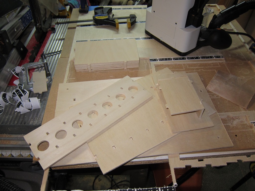
Eventually, I finished cutting all the pieces, and started cleaning them up:

IMG_9176

The shaper uses an upcut spiral bit so that it can easily pull the sawdust out; that cuts well, but leaves a fuzzy edge to the cut. I tried an offset technique where you do the initial cut a bit to the outside of the final line and the second cut right on the line, but the results weren’t any better. I’m going to explore whether a nicer bit would give a better result, but the result here is really worse than it looks. A couple of minutes with some 220 grit sandpaper and it cleans up nicely.

IMG_9180

A bit more time for cleanup, and I had a bit pile of parts:

IMG_9181

So, is this going to actually work, or was all that effort for naught?

Well, guess what?

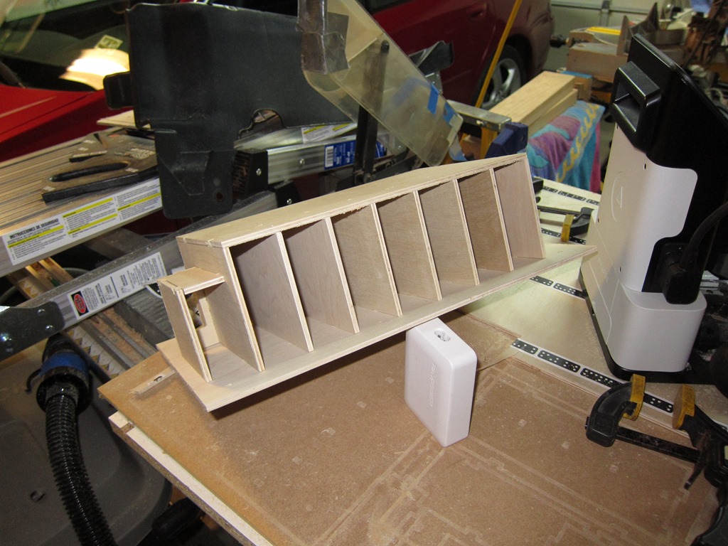
IMG_9182

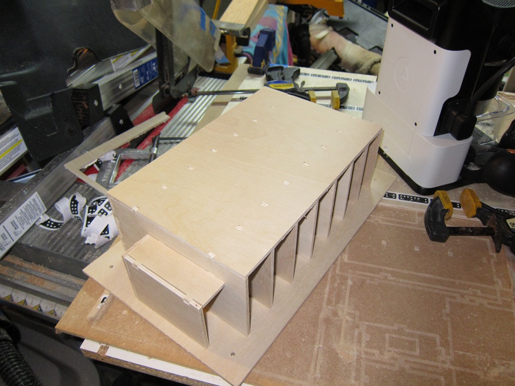
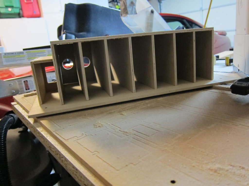
The fit of the tabs was very nice and it looks pretty good even without any glue to hold the parts together. Success!

IMG_9183IMG_9185

Next up is to look at all the joints and do a bit more tuning on the fit, especially on the hub holder in the left of the last picture.


Givin’ the dog a bone–USB charging station part 2

One of the realities of doing CAD work is that the real world sometimes intrudes…

Your laser cutter – for example – is limited to cutting a given size of material, and only in one plane. And it isn’t a perfectly thin cut, there is a little width to the laser beam.

For router-based machining, one of the problems is that the cutter is round, and often the cuts you would like to make are square. Here’s an example:

Image result for cnc dog bones

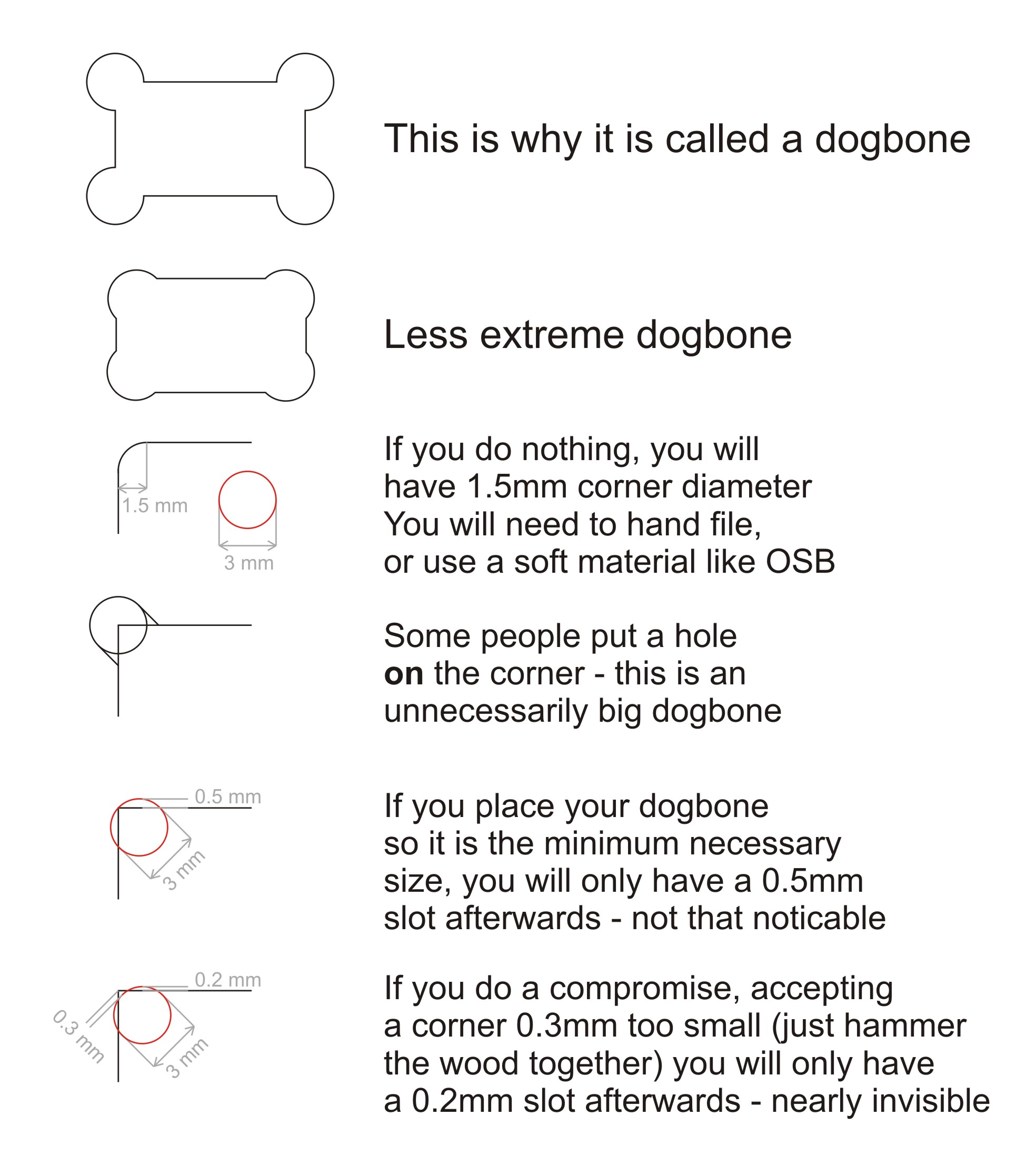
The part on the left is what you designed, and the part on the right is what you got when you cut it. There are a few approaches to deal with this; you can cut the corners out with a knife or saw, you can just pound the parts together and hope the material yields, or you can change your design so that the corners are cut out. It looks like this:

Image result for cnc dog bone examples

Hence the name “dog bone”. With the Shaper, there are a few ways to do this; you can either modify your design to include the dog bones, or you can do them on the tool, one at a time, kind of by hand. Since there are hundreds in this design, doing them on the tool did not seem very exciting.

There is an add-in for Fusion 360 that does dog bones, so I installed it and tried it on a few designs. Like lots of freeware, it’s a bit challenging; you either have to pick every corner where you want the dog bone, or you can let it pick the corners that need to be modified but this only works if the corners are vertical.

Oh, and it takes a long time. A *long* time. Like 5 minutes for a panel with just a few cuts if you mark them by hand, or 20+ minutes for one with lots of holes (19) where it figures out which corners to modify. This is made much more annoying because Fusion 360 does something that I thought wasn’t supposed to be allowed under Windows UI guidelines any more; the status bar that it shows brings the window to the foreground and selects it. Since this is happening about every second, you can’t do anything else on your computer while the dog-boneification process is underway. Which kindof gets in the way of making good progress, since you need to go and do something else.

About this time I needed to get some wood for the shelf, and I needed to know how much and how I would arrange it the cut pieces on the board. I found this tutorial to be very useful in understanding how to do that, and ended up with a nice layout on a 24” x 48” sheet that used a bit more more than half of the space.

Went to add the dogbones by selecting all 13 pieces in the and kicking off the add-in. An hour later it was still running. Two hours later is was still running, much more slowly. Left it overnight and came back to the autodesk crash dialog.

About this time I was really thinking of just using the Glowforge and forgetting about dogbones, but the whole point was to use the shaper, so I pressed on.

Went out for lunch, picked up some stock (birch plywood that was 4.7mm thick), rolled back to my 3-d layout, set the thickness of the stock, and went through and did each of the dogbones by hand-selecting each corner. After that was done, I ran the Fusion 360 plug-in for the Shaper Origin, which generated SVG files that I uploaded to their website (you can use a USB key if you’d rather). I was going to do the bottom part of the design; the last wide shelf and then the pieces that hang the hub underneath that, four pieces in total.


image

At some point, Fusion lost the material selection for the one piece, and I was too lazy to fix it.

IMG_9171

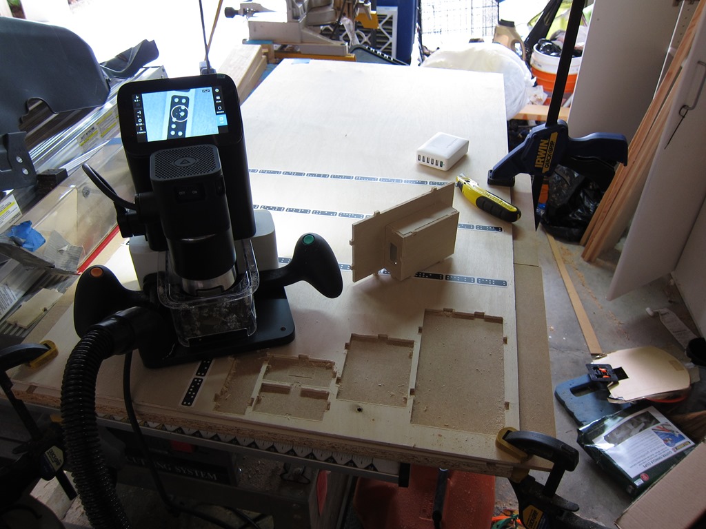
Here is the setup. Sitting on the router table portion of my BT3000 table saw, I have an extra ikea shelf (melamine and very flat), a sacrificial piece of MDF on top of that (you need to cut just through the material), and then the birch plywood on top (that piece was about $8). Across the wood you can see the “shaper tape”; this is how the vision system on the router knows where it is. The basic process to cut is:

  1. Move the router around so that it locates all of the domino-shaped shapes on the shaper tape.
  2. Load a design (in this case, from the online pieces I uploaded)
  3. Set the cut parameters (the size of the cutter you have in the router (1/8” in this case), how deep you want to cut on this pass (I did two passes, one at 0.125” and one at 0.2”)
  4. Do a “z – touch” so that the router knows where the top of the material is and can therefore judge depth.
  5. Move the router so that the line you want to cut is inside the circle.
  6. Turn the router on (using the physical switch on the head)
  7. Press the cut button (green button on the right handle), and wait for the bit to plunge into the work.
  8. Navigate the router around the cut.
  9. Press the retract button (orange button on the left handle), and wait for it to retract.

At that point, you can move to another cut that needs to be made or change parameters and recut the same line (deeper, for example).

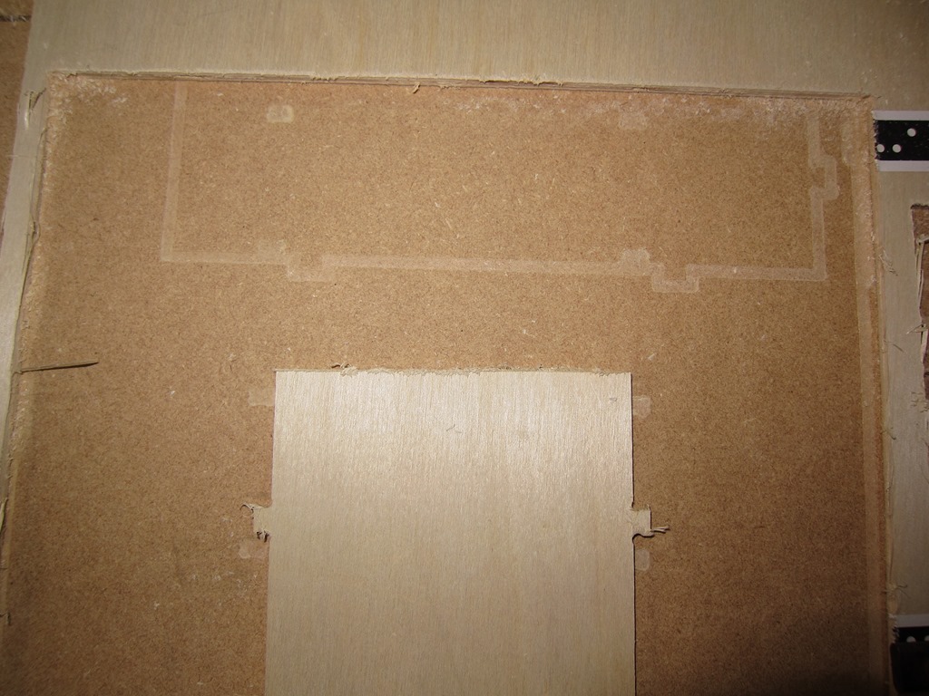
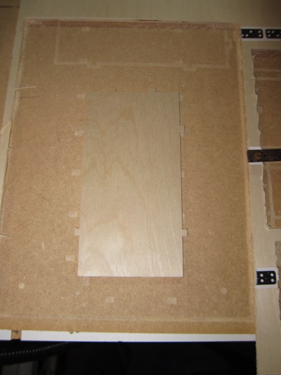
This worked really well, except for two issues. The first was that on my second cut, something went wrong, and on the cut, the router plunged the bit as deep as it could and then the software crashed (you can see the burned hole near the bottom of the workpiece). I had to turn off the router, pull it carefully out, and cycle the power on the shaper to get back. The second was my fault; I cut all the way through an outline before forgetting that the piece I cut had a cutout. Oh, and the software crashed again when it was just sitting there; the image on the display is a static one before I moved it to make the picture nicer.

And the result is…

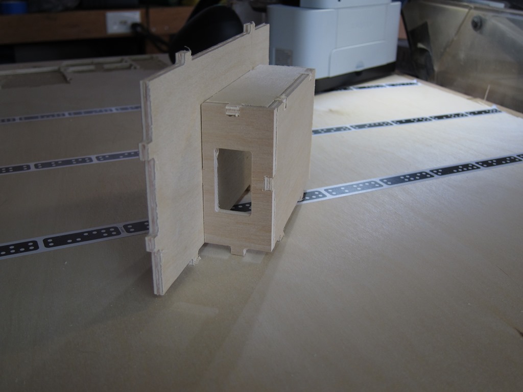
IMG_9172

IMG_9173

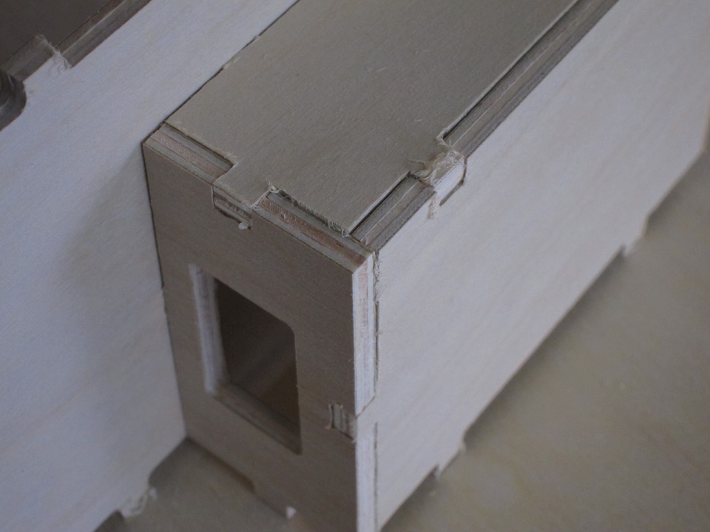
What do we see? Well, the first thing you’ll notice is that there is a lot of fuzziness on some of the cuts. The shaper uses an upcut bit, so that’s pretty common. The fix is to do the first cut at a bit of an offset back from the line and then do the final cut without the offset. Overall, the lines look really straight, which is remarkable given that a human is moving the router around.

What else do we see? Well, the joints don’t look very good, and there is a distinct lack of dogbones on them.

It turns out that I outsmarted myself. One of the tricks with dogbones in wood is to set the cutter size slightly smaller than the actual size of the cutter; that makes the dogbone a bit smaller but it still works since the wood has a little give to it. But… the Shaper knows the size of the cut you are asking it to do and the size of the cutter, so it just avoids cutting the dogbone path. I cut them by hand with a utility knife, but I was short of time so this is the result I got.

Finally, a couple of action shots with the hub in place:

IMG_9174

IMG_9175

Up next is to redo the dogbones for the remaining pieces *again*, and the cut them using the offset to see if I can get nicer joints.