Monthly Archives: September 2018

Fame and fortune by being slightly better

I’ve been attending our local lean coffee agile lunch (“lean lunch” sounds like something different…), and our discussion last Wednesday included something that I was meaning to write up for a couple of months, so here it is.

The setup is that we were discussion why agile adoption – XP adoption specifically – was so poor when the results were so obviously better.

This issue is the way management culture works and the way the incentives are structured. Let me posit two different groups.

The first lead – let’s call her Traditional Teri – does the existing company methodology well. Her team does code reviews, they do decent designs, they fix the right bugs first, and they take corrective action early.

The second lead – let’s call her Radical Rachael – is an agile advocate. Her team does decent agile; they do pairing, TDD where appropriate, story-based design, incremental releases, experimentation, etc.

Just to pull some numbers out of the air, Teri is about 20% better at getting software to market than her peers, and Rachael is about 100% better.

Who will be more successful at most companies?

We would all love for the answer to be “Rachael”, but the answer is, in fact, “Teri”. Almost universally. Because the cards are stacked against Racheal:

  • Rachael is doing something different and therefore risky. Just like “nobody ever got fired for buying IBM”, “nobody ever got fired for using the same slow and bug-prone development methodology”. If anything goes wrong, Rachael is at a big risk regardless of whether it is a result of her process choices or not.

  • They have different levels of peer acceptance. Teri is better than her peers, but only by a little bit and her peers can see how to get to that better level. Rachael makes her peers *look bad*. If she is doing the right thing, then they are clearly doing the wrong thing, but her peers don’t understand how to do what Rachael does nor do they want to. This is a built-in incentive for her peers to actively make Teri less successful or appear to be less successful because it makes them look better.

  • Teri is a joy for her manager Susan. Teri is never the problem team on projects, she has extra time to help out others, and Susan’s world is consistent and understandable. Rachael is a big pain for Susan, as she makes waves. Susan is forced to deal with different processes across the teams and field questions that come from outside the group as to why Rachael’s team is different. The outside discussions are very bad, as they make Susan look like Teri; now Susan has to convince *her* peers that what Rachael is doing makes sense, which isn’t good for Susan’s career. And like Rachael, Susan is running the same risks if anything goes wrong. The best thing for Susan to do is to actively hide what Rachael is doing, which means that Rachael won’t get credit for her team’s success.

  • Rachael is running a “no drama” team; because of her team’s process choices, they write very few bugs and they don’t have to work extra hours to get things done. But that looks like a team under the conventional process that is lazy and not working very hard, and since it takes a lot of effort to understand how objectively hard a team’s work is, the feeling that they aren’t working hard overshadows her team’s productivity. This is frankly a bit of a problem for Teri as well, but to a much lesser degree.

The end result is that Teri has much better career prospects at her company. It’s *easy* to make a case why Teri should get a promoted and why she would be a good choice as a second level manager, and the discussions that Susan has to have to convince others that Teri should be promoted are comfortable. And Rachael won’t get that promotion because Susan not only has a harder time making the case to Susan’s peers, it is not conducive to Susan’s career aspirations to have those process conversations.


Backyard controller design #4 – Software

The controller software lives here on github. My current software development environment is Visual Studio Code with Platform IO installed on top of it. It’s quite a bit better than the Arduino IDE for my usage patterns.

I’ve done my best to build a flexible and well-abstracted design. With the exception of main.cpp, all of the C++ classes are written in the include (.h) files so that I don’t have to deal with multiple files per class.

Here are the classes and a brief description of what they do:

  • Action – takes in a textual description of an action (on, off, toggle, plus some dim levels) and converts it to a numeric value. This is a nicer pattern to use than an enum as the parsing code can live here.
  • Device – an abstraction for a device that I want to be able to control. It has a text name, a group name, an output pin, and a timeout (in 10 mS units). If you pass it a name and an action, if will implement that action if the name matches either the text name or the group name of the device.
  • HardWiredController – the physical controller (not yet built) has a group of switches connected via resistors to the input line, giving a varying voltage based on which switch is pressed. This code uses the ADC in the ESP to get the current value, figures out what button was pushed, and performs the appropriate command.
  • Main.cpp – the main setup and loop code. Mostly just delegates out to other classes.
  • MainPage.h – the text of the web interface page for the controller
  • Manager.h – the manager for all the devices. It creates an array of devices and then handles dispatching commands to them, getting status strings, handling timeouts, etc.
  • OnIfAnyDevice.h – the 12V power supply needs to be turned on if any of the lights are on. This class looks at the state of the devices passed in through the constructor and turns itself on if any of them are on.
  • StairSensing.h – The program needs to turn on the house lights if the stair lights are turned on. This code tracks whether the stair lights have been turned on and switches the house lights on and off as necessary.
  • WebServer.h – The code that handles requests for the UI page and url action commands.

The main loop runs with a 10mS delay so that every time through the loop is roughly that long; that is needed to implement the timeouts in the device class. I could have done this in a more sophisticated manner but what I did is clear and good enough for the requirement.

The Manager and Device classes warrant a bit more discussion. They are use a software pattern called “Chain of Responsibility”; there are basically 5 devices that all look alike, and the manager just passes the action through to all of them and the device that the action belongs to deals with it.

This vastly simplifies the manager class – otherwise it would have to check every string and figure out which device to pass it to – and makes it really easy to implement group devices; the “lights” group refers to all light devices. It also makes it easier to implement the OnIfAnyDevice class, which otherwise would have required special case code.


Backyard controller design #3–Board & construction

In our last installment, we were trying to decide whether to hand-wire the controller or to go with the PC board. The PC board won out handily since it only cost $13.30 for the standard 3 boards from OSHPark.

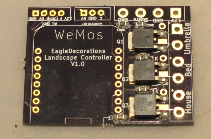
Here’s a picture of the board with populated with the 3 MOSFETs and 5 resistors. I did the solder paste application by hand since I only need to do one of these. Standard solder-paste since the MOSFETS may switch up to around 8 amps and therefore may get a bit warm.

image

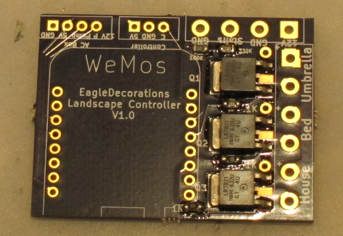
And here’s a picture after the reflow. Reflow done in my Controleo 3 toaster oven reflow-er. Looks just fine.

image

One little comment: One problem I had during layout was how to connect the top pin of the MOSFETS to ground in a way that could flow enough current from the front to the back. My first design started with a number of vias, but I didn’t like it. Then I realize I had an easier solution; I just use a single through-hold pad and hand filled it with solder. It will carry far more current than I need.

Build

In my original concept all of this was going to fit inside of a double-gang electrical outlet box, but I realized that a) I’d rather mix as little low voltage and line voltage as possible and b) the box I used was only half-depth, so no room. Which argued to use a box and mount it to the house. Here’s the one I chose:

image

It’s a good size and has mounting bars. I don’t really need the gasket because I’ll be cutting holes for the wires. $11.60.

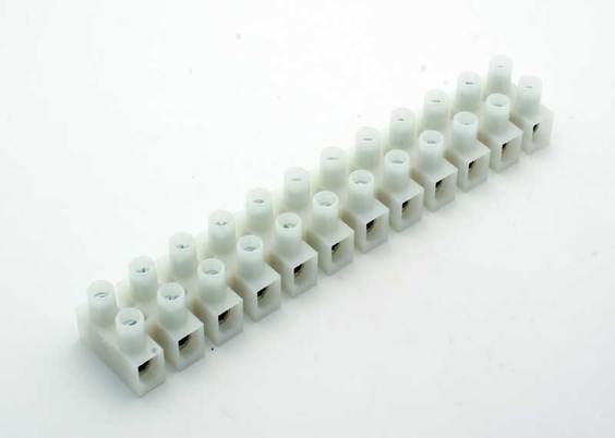
The next order of business was to figure out how to connect the big 12-gauge lighting wire to small connections on the board. I am lucky enough to have a good local Electronics store 15 minutes from my house (if you are in the Seattle area, Vetco is worth a trip), and that yielded a couple of terminal strips:

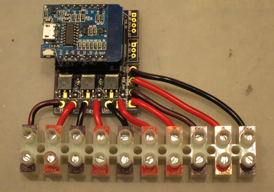
I think I bought two for $4.99 each, plus I bought some 18 gauge wire to go from the board to the strip (the big holes on the board can only support 18 gauge. Which led to this:

image

Those are all of the connections that take big wire, and the terminal strip color-coded with Sharpies.

Yes, I know I messed up the sequence; the 12V in at the lower right portion of the board really wanted to be there for each connection to the three 12V outputs. And it turns out that the wemos nodemcu layout I used was upside down, so the ESP-12 is hiding underneath the module rather than on top of it. There are female headers soldered to the board and male headers soldered to the nodemcu board. This allows me to easily remove it for reprogramming. Which was already required a time or two.

I used the same technique for the remaining controls I needed but they don’t map 1:1 to the board.

image

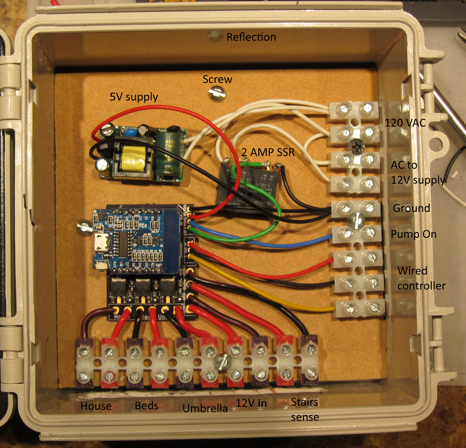
Here’s a few steps at once. I found an MDF cutoff and used that as the back of the board, and the screws that mount it also mount the terminal strips.

On the upper right terminal strip we have 120VAC coming into the box; that connects to a 5V power supply. There is a small 2AMP SSR that I had lying around that will switch on the 200  watt 12V power supply when it is needed. The “Pump on” output will connect to a similar SSR in the remote electrical box.

I did a full test of all the features, and they all worked. Well, except for the switching for the 12V power supply, which was broken by a refactoring I did in the software.

Umbrella lights

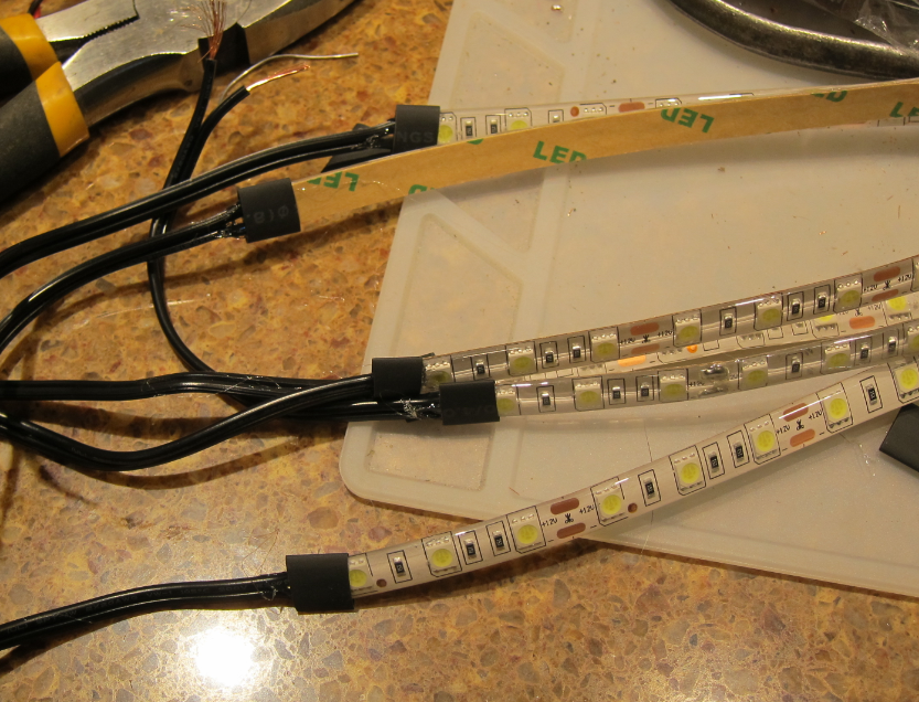
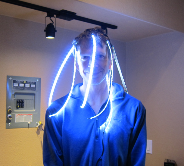
We have a shade umbrella with some chair under it, and one of the requirements was to have some light underneath it. I didn’t find any premade ones that I liked, so I bought 5 meters of 12V led strip and made my own. I made 8 strips that were 16” in length, attached wire, shrinkwrapped them, and then hooked them all together to a single supply. I only took one picture during construction:

image

But I did get this picture of them in operation:

image

Box installation

The box got installed on the wall and the various wires were hooked up.  This is under my covered kitchen deck so there is no real chance of any water getting in.

IMG_9330

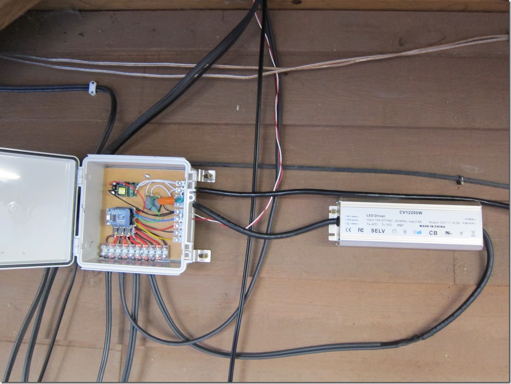
The AC comes in from the far right; that is a 15’ extension cord that plugs into a GFI with an in-use cover; directly under that is the 12 volt 16.5 amp power supply which then feeds back into the 12V input for the board. The red/white wire carries a 5V signal to the SSR in the electrical box that controls the fountain. The three main loads are hooked in along the bottom.

There are two things missing in this picture; the 12V line that used to run the stair lights is not hooked in, and the stair lights are not connected into one of the existing lines. It turns out the transformer for the stair lights does not put out 12V with no load; it puts out 17.3V. I did a conservative design on the board that would support 15V without damaging the ESP, but 17.3V was too much. I therefore built a small in-line voltage divider and used that to connect the stair lights in.

As of now, everything works fine delta one bug that I am chasing down.

I’ll write up a post about the software next.


Backyard controller design #2–schematic and board layout

My original plan for the controller was to do all the wiring by hand on a perfboard (“old school”); it’s not that complicated and I wouldn’t need to wait for a board. But I decided to do a pcb board to see how much it would cost and because I wanted an excuse to try out Kicad 5.0.

I started with the schematic:

image

We have the Wemos D1 mini (clone, actually) in the middle, with 5 outputs (PUMP, 12VPOWER, HOUSE, BED, AND UMBRELLA), and two inputs (STAIR_SENSE and controller). If you haven’t seen labels used in a schematic before, every pin with the same name is logically connected though there is no wire drawn between them.

On the right we have three drivers for the landscape lights using the NPN transisitor/MOSFET circuit I discussed in the last post. All of those outputs connect to the 6-connector header (screw terminal) strip.

On the upper right, the Wired_Controller1 header will be for a (possible) hard-wired controller for the lights and pump. It’s connected into the analog input of the ESP. In the actual handheld controller there will be four switches hooked across a voltage divider so that the switches will give 1V, 0.75V, 0.50V, or 0.25V when pressed. The ESP code will figure out which switch was pressed and therefore which action to take.

In the middle is the AC_Switching1 header. It contains the two outputs to control the remote solid-state relays for the pump and 12V power supply. It also contains the 5V and ground from the 5V power supply that will run the ESP.

On the left we have the parts for the stair light sensor. We have a voltage divider that will convert from the 12 V that will come in to a value that the ESP can tolerate. There was a bit of calculation there. The valid ESP8266 input voltages range from 2.5V (for the lowest guaranteed high value) to 3.6V (the maximum input without damage). We want to choose the voltage divider ratio to work well within that range.

My first choice was to use 330K for the upper resistor and 110K for the lower one; that would give a 4:1 ratio. That would put the lowest guaranteed high value at 2.5*4 = 10V, and the highest tolerable value at 3.6*4=14.4V. I decided I wanted a bit more range on the high side, so I opted from 330K and 100K resistors, giving a 4.3:1 ratio, and a voltage range of 10.75V to 15.5V. I considered overvoltage protection, but given the ampacity of the supply a simple zener likely wouldn’t be enough and I would need an SCR crowbar to handle overvoltage. I decided to skip it in this version as the power supply is a regulated one.

That’s all for the schematic; not really that sophisticated. Oh, the NPNs are really 2N2222; I chose the 2N2219 because it already existed.

image

Here’s the board layout. It’s a weird mix of through-hole and SMD components as I already had both the MOSFETS and the NPN transistors. I started with the header for the landscape lights because they will be pulling some hefty current; that meant I wanted to keep the traces short, and it also meant that I wanted to put the 12V in nearby in the upper right. The controlled where the MOSFETS ended up, which controlled where the NPN transistors and their resistors ended up. I reordered the output pins on the header so that they matched the order of the output pins on the ESP module; I could have remapped the pins as well but this was a bit simpler. The AC switching header also got re-ordered to make the connections simpler. And then I tightened things up a bit to minimize the size of the board. At that point, it was about $20 to do a board from oshpark, which was pretty much the cheapest I could find.

That’s relatively cheap, but I’m not excited about having to wait for it to make it back to me. The footprints for the screw terminals is not based on a header that I have; I bought some terminal strips before I decided to do a board design, but I need to buy some better ones for this sort of design. I need to get real terminals so I can get real dimensions, and I might see what I can do with all SMD devices; smaller terminals and transistors could cut the size of the board by 25%.

Two more things to mention. You’ll notice that there is not a copper pour for the ground. It’s probably not required for a board operating at these speeds, and I would have to be careful around the ESP8266 antenna because having copper underneath it would mess it up.

I did another layout with through-hole resistors in case I wanted to hand build it:

image

Back to the problem in hand… If I was willing to wait for a PCB to show up, I could wait for some new MOSFETS and transistors, and that would certainly make things smaller. So, I went MOSFET hunting, and I found the IRLR7821PbF, available in a TO-252AA package at $6 for 5 MOSFETS. Sound good.

I pulled up the datasheet and started reading. It’s pretty similar to the IRLB8721 that I had currently specified, but on Page 2 I found the output characteristics graph:

image

Looks like the one we saw in the last post, right? Except this this one starts at 2.5V and 2.7V curves. Looking at the 3.0V curve – to be conservative – and we see that with 10V drain to source, we can get a little more than 10 amps of current at a junction temperature of 25 degrees. At 3.3 volts, it’s closer to 12 amps.

What that means is that we can drive this MOSFET directly from the ESP8266. We can lose the NPN transistors to drive the MOSFETs plus one of the resistors.

So, off to do a new design with this MOSFET. I decided that I’m going to mount the board, run wires from the board to some terminal strips that I have, and then hook the real wires to those terminal strips. That will make it easier to hook up and I can make the board smaller so that it will be cheaper.

After a lot of iteration, here’s what I end up with:

image

It’s about 30% smaller than the original board; part of that is done by letting the ESP board overhang the end of this board, but they will both be in an enclosure (3D printed, I think), so there’s no harm in that. All of the heavy current stuff is contained on the right side of the board.

I first head to OSHPark, which tells me the board is 48mm x 37mm. That’s less than half the size of a credit card, so, tiny. They will make me 3 boards for $13.30, and oshpark does really nice boards, with an ENIG finish, but they take a couple of weeks to show up. I head next to pcbshopper.com and find nobody cheaper, except allpcb.com. I used them for the boards in my dodecahedron and they’ve done good work, and I can get 5 boards in 5 days for $10, shipping included. They must be blackmailing DHL to be able to ship so cheaply.

I’m trending towards OSHPark since I need to order the new MOSFETs in anyway.


Passport2Pain 2018

This is my third attempt at the “Idiot Level” Passport2Pain course, and my third completion (2013, 2016, and 2018). In 2016 I left my GPS at home and apparently didn’t bother to write anything up, so any comparisons will be to 2013.

My wife and I went over Friday afternoon to have dinner with and stay at the house of one of our ski instructor friends, who very conveniently lives 15 minutes from the starting line. I slept poorly as is my usual before big rides, but got up, skipped breakfast, and we headed over to the starting point.

After the usual wait and ride introduction (“In thinking about fundraisers, we had an idea. It wasn’t a *good* idea, but it was an idea…”), we queued up to start. They start with 4-5 riders every 30 seconds or slow to spread the riders out. Contrary to the pre-ride description, they made no effort to actually send out the idiot (80 mile) route riders first; I knew to line up near the front but I would have been upset if I had to wait 40 minutes to start. Considering the difference between the two routes is well over two hours, they need to do better at this.

We pedaled away from the start at Jensen Point, which is on this weird little spit. I started talking with a guy in a t shirt, jersey, and cutoffs; he had forgotten his clothes. He pulled ahead and took the first turn to exit the park area and immediately pancaked on this left side.

It had, you see, rained the night before and it was 57 degrees and cloudy. So there was still a bit of moisture on the road, and likely a bit of oily film.

He was fine and we rode off to start our quest, and I made a mental note not to ride too near to him – or any other riders – while the roads were wet.

I generally describe P2P as riding all the way around Vashon island and taking every road that goes down to the beach.

image

That is hyperbole. There are, in fact, numerous hills that will will not ride down, but we will ride down a large number; overall, there are 25 climbs on the ride, most of which are in the 200-300’ range, plus a bunch of small hills and rollers. If you are doing a ride like RAMROD, there are really only 3 hills (Paradise, Backbone ride, and Cayuse), and that’s how you track your progress. On P2P they do have checkpoints where you get your passport stamped, but there are 18 of them.

My approach is to just ride; I know what the parts are, and I know that I need to ride slow because the last set of hills is pretty bad.

So, we head off, do a short climb, and then descend down to the first real climb, which is a weird down and up. And quickly run into our first issues.

We roads and steep climbs do not mix. Going down you can just take it easy, and even with disc brakes I’m taking it easy on the still wet roads. The problem is when you start having to go up again. I can sit and ride up a 15% hill pretty easily and tough out a 20% hill, but it’s nice to be able to stand. Except if you do that, your rear wheel spins up. Which is bad. So, you just need to sit and suffer.

The first 5 stops go by pretty fast; slow and careful on the descent, and then doing my best on the climbs to stay smooth and keep calm. This part of the ride is the warmup, though it’s a little nuts that the warmup has 8 main climbs and 2500’ of up over the first 25 miles. We then have 5 miles with a climb or two, and then turn off onto Burma Road.

Burma is a mostly paved goatpath that rolls up down and around; they laid asphalt with doing as little grading as possible. Burma has one easy climb – say 13% or so – and then two hard climbs. They are aren’t very high, but they are well in excess of 20% (my GPS said 27 but I really don’t think they are quite that bad). The general way to attack Burma is to be able to ride slowly – say 3MPH – while standing, and if traffic permits, do a slight weave back and forth. It’s not categorically different than “The Widowmaker” in Sufferin’ Summits, and it’s quite a bit shorter, though it’s barely one lane wide.

That is what I did on two previous rides, but Burma is fully shaded and quite wet this year. After spinning the rear up despite being really gentle, I just ride slowly and muscle my way up. Not fun at all and I’m stressing my legs much more than I hoped, but it’s either that or just fall over (I don’t think I could unclip and stop), so I ride up both pitches apprehensively and then get to meet the devil.

Almost directly after, there’s another hill with a torn up descent at the bottom where you can barely stop and an ascent where you can’t stand, but that’s par for the course. Later this same hill has a solid 20% section, but luckily that pavement is dry and a real road so you can tack/paperboy back and forth and stand if you want to.

There’s one more loop down to the water, a spin along the main highway, and we hit the lunch stop.

I’ve been snacking a bit along the way; I have some nuts and I’m eating small amounts of carbs, and that’s working great except for 5 peanut M&Ms that give me a knot in the stomach.. At this point, I’m pretty tired and deciding whether to do the 55 mile or the 80. I eat the fillings of a very forgettable BLT and a bit of bread and then stop at the Thriftway for a Coke Zero but am stuck with a Diet Coke.

I mean, seriously, what are they thinking?

I text Kim to let her know where I am (she is doing a ride into the village for coffee) and tell her I’m 50/50 on which variant I will do and I’ll text her when I decide.

I roll out. There’s a small and ugly climb on the next section, but this one is dry and I’m feeling decent until my right hamstring starts to cramp near the top of the hill. I stop, dig some electrolyte capsules out of my pack, and wash them down. Then it’s off to Evil Twin #1 and #2. They really aren’t that bad and I’m climbing a bit better after food and Diet Coke. The second stop has chips and guac, and I have a few, heavy on the Guac.

And that’s all the hills on the 50 mile/6500’ route, so I need to make a decision. My toes and left shoulder hurt a little, but my legs are feeling okay, so I stop to text Kim and press on, onto Maury Island, and get ready to grit my teeth. Because as tough as the Burma Road section is, this section is a real bastard. It looks like it won’t be that bad – there are only 5 stops – but it’s a full 30 miles and over 3000’ of up.

We work our way through 14, and then descend down to 15. This has the added pain that as I near the stop, I ride by our friend’s house and out in front my Outback is parked, with a perfect bike-shaped space in the back, beckoning to me. I manage to avoid the temptation, but man, the hill out is a major bitch, and I’m tacking back and forth for all I am worth. And it’s not like I’m getting passed much, since all the fast people are in front those near me are bound together in a brotherhood and sisterhood of suffering and pain.

On the plus side, I’ve had no more cramping issues, so there is that.

Then there’s an ugly descent, and we ride into Dockton. We have three stops left, so three hills, right? How bad could that be?

I hate Dockton. We are down right at the water, but we climb 300’ up to the top of the island, and then we descend all the way to the water down yet another sketchy, wet, and slightly mossy road. For a measly stamp on our passports. Then we climb out that same damn hill, though the way from the water is worse.

And then – and this is the wonderfully terrible part of this ride – we do it again. Climb 200’ up into the hills, all the way down to the water, collect our penultimate stamp, and then it’s another 250’ climb back to where we started.

And the pain of Dockton is over. At this point I’m feeling pretty good; I *know* can finish the last hill, and then there are only a few rollers after that. I ride up a 150’ uncategorized hill – I mean really, it’s only a 7% and it feels very easy – in company with another rider, and I form a plan.

There is only one hill left and my legs feel like they have a little something left. So, we come to the last hill – 330’ of fun or so – and I start climbing hard, which is somewhere between 230 and 280 watts as the hill steepens and eases (my earlier target was <200 watts if I could). My data shows that I’m 43 seconds faster than my 2013 ascent – a full 9% faster. I get to the top, have a little bit of popcorn, and spin out to finish the ride.

The way back is about 4 miles with only a few rolling hills, so I push my speed up a bit. And then, finally, I finish, and get to have some well-earned barbecue with my spouse. It’s pretty good in the “Puget Sound Barbecue” category, but the brisket needed another couple hours in the smoker.

Analysis

Strava says I pulled 12 PRs on the route, and 9 of those were on hills. That makes me pretty happy, and I felt strong for most of the ride. It’s so much nicer and prettier than Sufferin’ summits.

Stats:

80.81 miles
7:11:46 riding time
9,949’ of up
11.2 mi/hr average

How does that compare to 2013? Well, in 2013 I rode 1.5 miles farther, which was probably due to more back-and-forth across the road, and finished in 7:13:27. My average speed then was 11.4 mil/hr, faster than this year, but my speed on descents was at least 25% slower than before because of the wetness.

2013’s ride was done on my Trek Madone, a fine bike for making speed but it was pretty harsh on the crappy Vashon roads. This year I was on my Roubaix with disc brakes, a frame tuned to soak up vibration, shocks in the seat and steering head, and 28mm tires at 80 psi. It was gloriously better; the stuff that really would have beat me up last year was still annoying but not too bad.

image