Monthly Archives: November 2018

The word for the day is “Thixotropic”

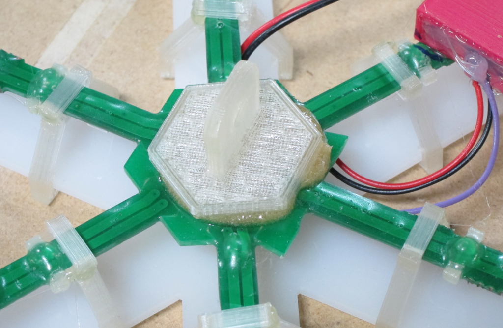
I had a small gluing project to do today; I needed to attach a small 3d printed pad eye to the back of my animated LED snowflakes (project info here). The pad eye looks like this:

image

The pad eye is printed out of PLA and is about 1.25” inches across. I needed to attach it to the back of a printed circuit board. Which would make my adhesive choice seem simple, but there are two complications:

  1. There are wires soldered onto the PC board and that part of the board is not flat.
  2. The boards are waterproofed in epoxy, and the coating is has some variation – perhaps 1/16”

That means that I need an adhesive that will bond well to the PLA and epoxy and fill the gap in between the two surfaces.

My first thought was to heat up the hot glue gun and use it. It works fine as a gap filler, but it’s not great in a thin layer between two big surfaces; it’s too easy to have the glue cool too fast and not really bond to the surfaces.

My next thought was to use epoxy. I have several epoxies in my workroom; they are the small hobby shop versions that come in small tubes or bottles. I really don’t like them very much; it’s hard to get the mixture ratio right and in this application they tend to be too runny. And they smell.

Out in the garage I have my serious epoxy:

That’s leftover from a custom subwoofer project I did a while back. It’s really easy to use; one pump of resin plus one pump of hardener and just mix it together. I have the 206 hardener, which is classified as a “slow” hardener; 20-25 minutes of pot life (useful life after you mix it before it starts to thicken up too much), 10-15 hour cure, 1-4 days to maximum strength. The nice part about serious epoxy is that it’s tunable; you can use the 205 fast hardener which cures in 6-8 hours or the 209 extra slow hardener with much longer pot life and a slower cure.

Anyway, I really like this epoxy, but it is really runny, so it won’t work for this application.

Or will it?

Welcome to the wonderful world of epoxy fillers. There are a lot of different fillers out there – here’s a nice article by System 3 (another epoxy company) that describes them and why you would use them – that can modify the properties of epoxy considerable. For this use, I am interested in fillers that modify the viscosity of the epoxy, and specifically interested in fillers that make it thixotropic.

A thixotropic fluid is one that flows when you apply stress to it and then stops flowing when that stress is used. The most common example used is catsup, but I think that peanut butter is a better example; you can make it flow around but when you are done, it sticks where you want it. And it’s sticky, like epoxy. That is a wonderful property for an adhesive; just stick it where you want and it will stay there until it cures; no drips or sags.

There are a few common thixotropic fillers; ground silica (known as cab-o-sil or aerosil), plastic minifibers, and – my personal favorite – wood flour.

image

This particular wood flour came from the little bag on my random-orbit sander, which is why I like wood flour; I generally have it sitting around. Note that it needs to be very fine; sawdust from cutting will probably be too coarse. The wood flour will make the epoxy wood colored; if you would prefer it to be closer to clear, the ground silica or plastic minifibers will work better.

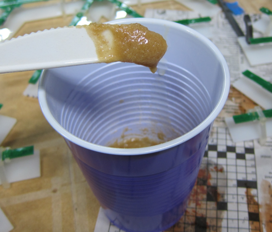
Mixing it is pretty simple; mix up the epoxy, add a little wood flour, mix it up, and examine its physical properties. If it drips off of your mixing device, you need more wood flour. If it sticks like the aforementioned peanut butter, you are done.

image

I like to use small plastic cups for my epoxy mixing and plastic silverware; they are easy to find and disposable, and since I use the dispenser pumps to get the right amount, I don’t need to do any measuring in the cups.

All that is left to butter the epoxy onto the PLA pieces, gently press them in the proper position, and wait for the epoxy to cure.

image


Candle lantern design thoughts…

I’ve been spending some time doing a design in Fusion 360 for a laser-cuttable lantern, and I’ve discovered a few things. I’m recording them here to help others and to remind myself when I come back to this in a few months/years.

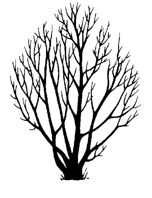
I started with a simple outline drawing of a tree that I wanted to use as the inset for the side panels:

Alder

I need to get that into Fusion in a way that works. Here’s what I came up with

From 2d to 3d

There are a couple of different approaches to doing this. If you have something that is simple, I recommend the “trace it yourself method”. In this, you insert the picture into Fusion as a Canvas (Insert->Attached Canvas), and then draw an outline in a sketch using it as a guide. I used splines and did a reindeer and rabbit outline pretty quickly, and then nice part is that manipulating the splines after that is simple and quick.

That was going to be a ton of work with the branches and I was both lazy and worried that it would be too complex to work well. So I took the alternate approach:

  1. Load the image into Inkscape and save it as an SVG.
  2. Use SVGtostl.com, upload the svg, and specify how thick you want it to be. You will be able to change this later though it’s a pain, so try to get close.
  3. In Fusion, in a new design, choose Insert->Insert Mesh, and choose the file.
  4. Switch from model mode to mesh mode.
  5. In the browser tree, right-click on the mesh and choose “properties”. My trees end up with 13000 facets, which is about 3 times as many facets as I wanted.
  6. Use the modify->remesh and modify->reduce options to get down the count that you want. You will probably have to experiment a bit to get it to work right. Start with Remesh, and preserve sharp edges and boundaries. You now have a mesh.
  7. Switch from mesh mode to patch mode
  8. Select the mesh in the browser
  9. Modify->mesh to brep. This is changing from the mesh representation – which you can’t really modify in Fusion – to the brep representation, which you can. This may take a while. At this point, you have both a mesh and brep version of the object in the tree. Delete the mesh version as it’s just taking up memory.
  10. If you look at the brep version, it has a ton of faces on it. This will slow things down, so it’s nice to clean up the faces. Modify->merge, choose “select chain”, and then click on one of the front faces. That should select all the faces.
  11. Click “ok. That’s going to sit and spit for quite a while, but eventually it should finish and you should just see one common face. Or maybe Fusion will hang and you’ll have to restart it.
  12. Convert the resulting body to a component, and save it.

Using the resulting design

The resulting design is very complex and will likely kill Fusion. It tried to use it to create panels for all four sides of the lantern, and that was a full failure; it would take a full 30 seconds to render.

What I ended up instead was doing the full design in Fusion without the complex branches. It looks something like this:

image

I designed one side of the lantern and then used pattern on path to duplicate it around 4 sides to make sure everything worked, and then used it to cut the top and bottom for the tab holes.

Then, I took the original side that I designed, converted it to a component, and did the compositing of the side and the branches in a design that only had those parts. That worked well from a performance standpoint and since all four sides are identical, I can just cut the single one four times.

To get this to work I had to move the components so they were okay left/right, use align to move the frame so the front is coplanar to the front of the branches, and then extrude a couple tools to cut off the branches where they were too wide for the frame.

image

Cutting on 2.7mm plywood (was supposed to be 3mm….) took about 5 minutes for each side, and a couple of minutes for the top and bottom.

Here’s a totally uncleaned/unsanded version. It would also look nicer if I taped the wood to protect it:

image


Cat bed elevation device

We have a couple of heated for out cat to hang out in, which she really likes. One of them lives in the living room near the windows, but unfortunately if she is in the bed she can’t see out the windows.

What was needed was a way to elevate her so that she could see out. Which seemed like a perfect opportunity for some CAD and CNC.

The design

I fired up Fusion 360 and started playing around. I started with the basic dimensions; the top would be 18” square (the bed is really pretty big) and it needed to be 11 inches tall. Then it was off to build the basic model.

In the past, I’ve used “through tabs” which are easy to do but not aesthetically pleasing. In this design, none of the tabs go all the way through, which makes it a lot nicer looking.

After a couple of hours I had the basic design:

image

The bottom cutouts on the ends are so that there are four discrete legs for support, and the holes are to make it look a little more interesting. I played around with another slot farther up, but decided not to for reasons that will later become apparent. Note that there are no visible tabs.

Here’s the inside of one of the ends:

image

This shows the cutouts that I will make for the end; there is the outline and slot that go all the way through, the recessed pockets for the tabs from the sides, and then the tabs that will go into the pockets cut into the top.

There are “dogbones” cut at the corners; these are needed so that the rectangular corner of the tab has someplace to go. This is using the new “minimal dogbone” add-in for Fusion 360, which is a great improvement over the previous version.

Material

I went to my lumberyard (Dunn Lumber) and procured a sheet of 12mm baltic birch plywood for $30. It comes in an exceedingly inconvenient 5’x5’ size, which means that I cannot fit it in the back of my pickup. I can, however, tie it to the top of my outback.

Cutting

I trimmed the 5×5 sheet into a 2×5 sheet for this project and a 3×5 sheet for later projects, and then set up my workspace. It’s a melamine shelf with some thin sacrificial sheets of 1/8” MDF on top and then the actual wood clamped on top.

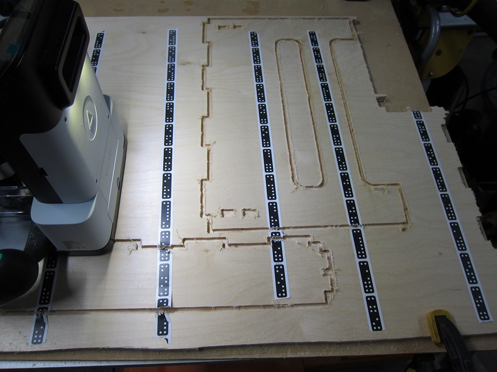
Shaper suggests that you use double-sided tape to hold the wood down, which is a really good idea that I keep forgetting to do. I added the domino tape so the shaper can figure out where it is, and started cutting.

It takes multiple passes to go through 12mm stock, and after a few options I settled on 5mm, 10mm (the depth of the pockets), and 12.3 mm to cut through.

Here’s a shot partway through the cutting:

IMG_9366

I took that picture because the Shaper crashed in the middle of the cut. It luckily remembers the layout so you can keep cutting when you startup, but you sometimes lose tracking before it finishes retracting the bit so there are small mistakes in the cuts.

I had about 8 crashes while cutting the parts for this. Unlike previous projects – where it would crash only while cutting and in reproducible situations – these crashes seemed to be much more random. I’m working with Shaper on it but haven’t figured anything out yet; in this case it cut flawlessly for about 45 minutes before any issues showed up, so I suspect it’s heat related.

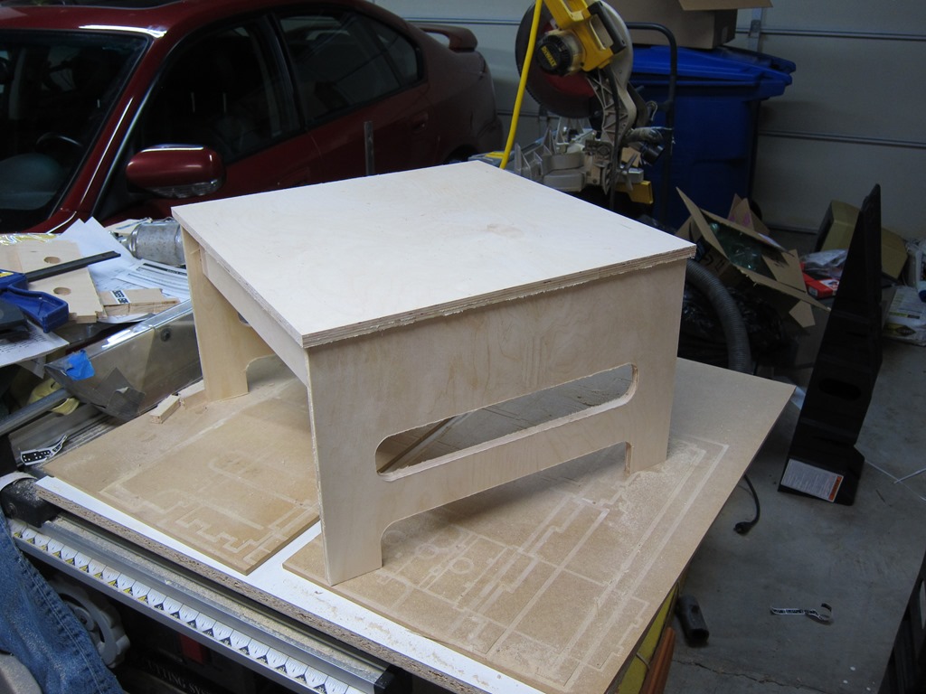
Anyway, eventually the last part was cut, and I could fit the pieces together. One of the joys of the CAD-based approach is that if you don’t make mistakes, things just fit together. I used my soft-blow hammer and ended up with this:

IMG_9371

Definitely looks like a stool. You can still see a lot of fuzz that needs to be cleaned up and an overall sanding is in order.

It was at this point I realized that I messed and hid the nice surface of the plywood up instead of down, which means the display faces have a number of patches that should have been on the inside.

Sigh. Well, my cat won’t mind.

I spent a lot of time sanding and de-fuzzing the project, and it seemed like things were okay.

Identification

As you can see, it’s definitely a stool, but it’s not a definitely a cat stool. It needed something so that our cat would know that it was her.

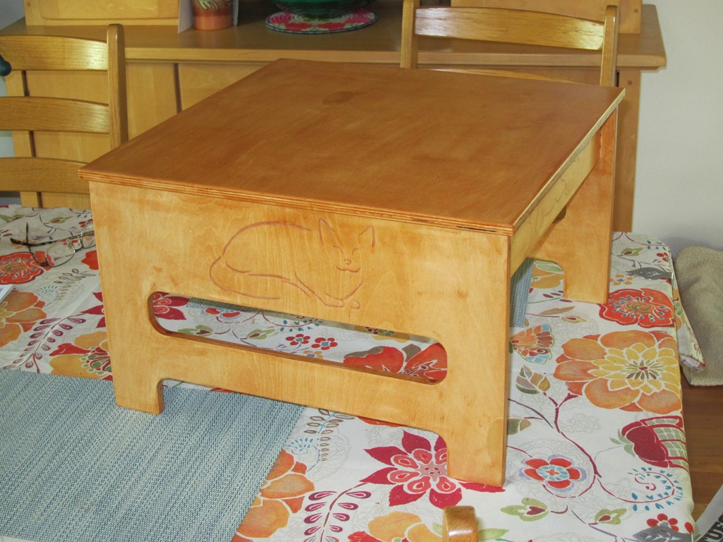
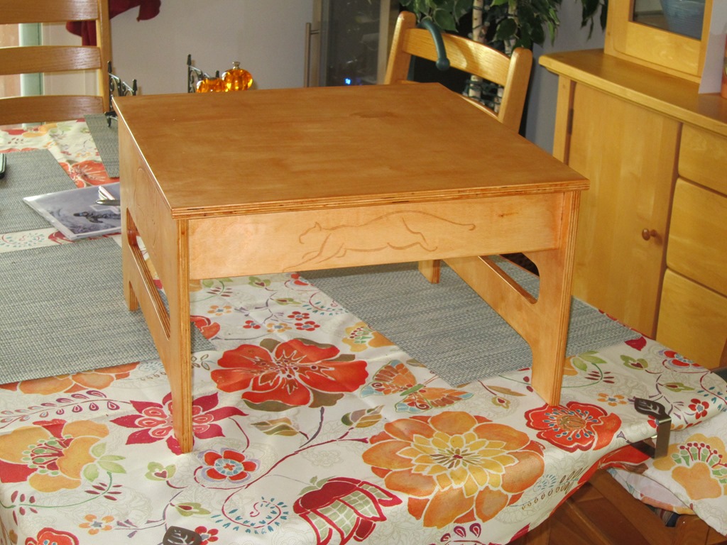
After spending approximately 20 hours looking at cat drawings online, I came across a set that were very minimalist, and I picked four, two for the ends and one for each side.

Those got cleaned up an image editor and then engraved into the wood with my GlowForge. That took about 45 minutes.

Assembly

The sides were glued together, assembled temporarily into the top for alignment, and clamped until they were dry. Then this was repeated to glue the sides to the top.

Finishing

I wanted something a little more golden than the natural color, so I wanted a bit of stain. I decided to kill two birds with one stone and get a polyurethane with stain.

Bad idea. Maybe a good idea if you are spraying the finish, but applying by hand every slight difference in thickness shows up as a difference in color, and if you get any runs they look pretty bad.

Lesson learned for later. After the first coat dried, everything got sanded with steel wool to knock down the raised grain, and a second coat finished it off.

IMG_9377IMG_9376

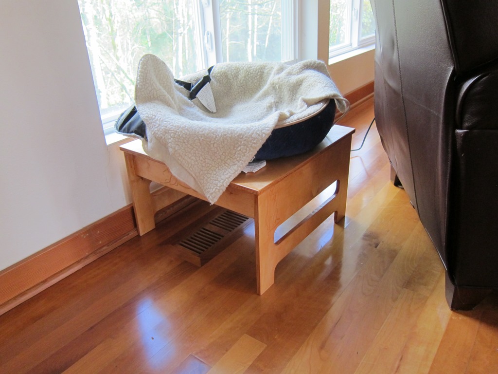
And an action photo:

IMG_9378

As I have not obtained a model release from the cat I am contractually unable to show photos of her in the bed.

Shaper project is here.