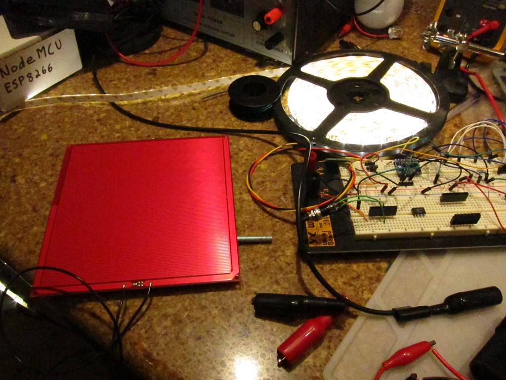
After I wrote the stress test article, I decided to put a voltmeter across the drain and source of the MOSFET and figure out what the voltage drop was. I hooked up the output to an LED ornament, watched the brightness cycle up and down, and put my probes on the MOSFET.
What I expected was pretty simple. In the sweet spot of the MOSFET I’m using, it claims a Rds – resistance between drain and source – of 10 milliohms. That means I should expect a voltage drop at 5 amperes of:
V = 0.01 * 5 = 0.05 volts
That low voltage drop is one of the reasons to use a power MOSFET; a bipolar transistor would have a voltage drop of about 0.6 volts, and therefore waste more power and get hotter.
The voltage jumped around a little, and settled down at full brightness:
0.8 volts
Okay, that is really unexpected; I played around with different voltages, and I still got 0.8 or 0.9 volts.
My first thought was that the MOSFETs that I got from Ebay might be counterfeit, so I waited for my order of real parts to show up from Arrow, built a new board, and it read:
0.85 volts
This is really confusing, so I asked a question on Reddit’s /r/AskElectronics subreddit.
The first answer I got was that it might be the base diode because I had the MOSFET backwards.
So, I pulled out the datasheet for the MOSFETS and looked at my schematic and board in Kicad. As far as I can tell, everything is wired correctly.
A deeper answer suggested that if I was doing PWM (I had been testing at brightness = 250 because I knew that would be more stressful for the MOSFET than always on), I should test with always on. It also talked about gate capacitance.
<digression>
This is one of those cases where real devices diverge from ideal devices. FET stands for “Field Effect Transistor” – current through the source and drain is controlled by the field on the gate. You establish a field by the flow of current to charge it up to an appropriate voltage. The amount of current it takes depends on the gate capacitance (described as “Input Capacitance” on the datasheet). For the MOSFET to turn on, you need to flow enough current to establish whatever voltage you want on the gate.
Or, if you think of the gate as a capacitor, it takes a bit of time for it to charge. In my case, the time it takes to charge will be controlled by the pull-up resistance and the capacitance.
Let’s say we are running at 5V, and our MOSFET has 1nF input capacitance (pretty close), and we are charging through a 10K capacitor.
This calculator says that the time constant is 0.00001 seconds, or 10 microseconds.
</digression>
So, I went and changed the animation code to run all the way to full on – luckily my code is running on an ESP8266 and animations can be changed over WiFi – and rechecked the voltage drop.
Would it surprise you if I told you it was 0.8 volts? Probably not at this point…
Perhaps it’s my voltmeter; I have a nice Fluke but how about if I try using my oscilloscope (a Rigol DS1102D I picked up a while back)?
So, I powered it up, hooked it up, and looked at the waveform across the load. I showed the a nice PWM waveform…
But wait a second… I had updated the animation.
My debugging rule is that when things seem unexpected, back out a level and retest the assumptions. Usually one of those is wrong.
I started with my controller code. I suspected the gamma mapping code, so I added some Serial.println() statements and verified that, yes indeed, the colors were getting set to 255. So, that part was fine.
I next suspected the support library I use (the rather excellent NeoPixelBus). I read through a bunch of source but didn’t seem to be any issues. The code all looks fine…
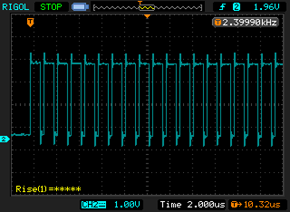
Was the data getting to the WS2811 correctly? So, I fired up the scope again and hooked it to the data line. On full on, the data looks like this:
The WS2811 uses an encoding scheme where a short positive pulse means “0” and a long positive pulse means “1”.
That is a full string of ones; you can’t see all 24 of them, but trust me when I say they are there. You can see this switch back all the way to all zeros as the animation progresses.
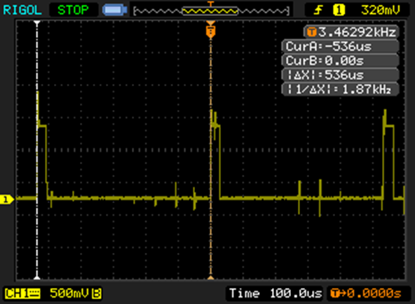
So, the software is telling the WS2811 to go to full bright, but it is still turning off for part of the cycle. Here’s the output straight from the WS2811:
That little positive spike is 29.4 microseconds, which is about 5% of the 536 microsecond cycle time, so full bright is only 95% bright.
The cursors on the capture show the start of two sequential PWM cycles, and the scope nicely tells me that it’s updating at 1.87 KHz. Which is another weirdity, since every source I’ve seen suggests that WS2811s update at 400Hz.
At this point I’m beginning to wonder if I have a WS2811 clone. I thought it might be the same IC used in the SK6812 ICs, but the claim is that they have a PWM frequency of 1.1KHz which is less than I am seeing.
So, it’s off in search of some real WS2811s. It is really easy to buy cheap ICs made in China but is surprisingly hard to find an authorized source. There are lots of sources on aliexpress, some looking pretty shady. Octopart found me a 10-pack from Adafruit for $4.95. I finally found lcsc.com, which specializes in this sort of thing, and ordered some. They look to be WS2811S chips, but I can’t find any information on what the “S” means. More on that when they show up.
Back to voltage drop…
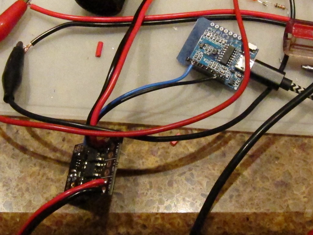
Since the WS2811 wouldn’t go into “full on” mode, I needed a test setup to do my testing. Here’s what I came up with:
In the right middle is the MOSFET, with clips connected to the lead and the body. In the picture, it is running only the LED Star, which pulls 145mA of current.
One of the fun things about MOSFETS is the gate holds onto the charge, so if you just touch the gate to 12v, it turns on and stays on. Touch it to ground, and it turns off, and stays off. I measured the voltage drop across the MOSFET.
I next decided to hook up my test load. I started with a single 50 watt bulb, a 4 amp load. I carefully hooked it up in parallel with the led star, and…
There was a loud “crack” and the led star went out. No magic smoke, but the MOSFET was toast. The gate was floating, and there wasn’t enough charge there to put it firmly into full conduction, so it was in the linear zone and quickly overheated, melting the plastic on one of my clamps. So… replace the MOSFET, make sure the gate is attached to positive, and try again. That worked, and the MOSFET was only mildly warm. Let’s try two bulbs for an 8 amp load. That worked, *but* there is no heatsink and it got hot pretty fast, so I unplugged it before it got too hot.
I collected some data and figured out that the Rds was about 90 milliohms, which is a lot higher than the 10 milliohms I expected. That was a mystery for about 8 hours, until I was writing this up and realized that I was measuring the voltage drop at the ends of the leads connected to the MOSFET. The thin leads.
So, I went back and measured right at the MOSFET, and got a Rds of 7 milliohms, a bit better than the 10 milliohms that was spec’d. So, yay!
Faster switching
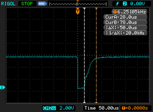
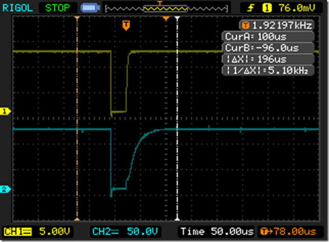
Returning to our somewhat slow switching, here is what I saw:
The negative transition is when the transistor turns on; notice how effortlessly and quickly it pulls the gate voltage down. And when the transistor turns off, note how long it takes it for the gate voltage to charge back up. It’s roughly 10% of the overall cycle time.
Which is a bit embarrassing; I chose the 10K value as a typical pullup value, not thinking about the fact that this was happening on every PWM cycle. It can only supply about 1 mA of current.
The most obvious thing to try is to replacing it with a 1K resistor. That will result in 10mA of current and should switch roughly 10 times faster. Can the transistor handle it? The datasheet says that the 2N3904 can handle up to 200 mA continuous, so that will be fine. Is the base resistor okay? Well, transistor has a DC current gain of at least 50, so that means we need a base current of 10mA / 50, or 0.2mA. The 5V from the WS2811 will push about 4 MA through the 1K base resistor, so that’s way more than enough. It would probably be fine with a 10K base resistor, actually.
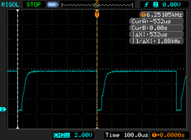
I took one of the boards and replaced one of the 10K resistors with a 1K resistor and then looked at the gate drive:
In case it’s not obvious, the top version is with the 1K resistor and the bottom one is with the 10K resistor. More than good enough for my application.

