My skiing penguins project has been up and animating for a few weeks, and I thought I’d write down the process for others so that they can learn from what I did. And also so I can remember what I did and why. There are some other blog posts that talk about some of the specifics for the sequence controller I built.
First off, there’s a video here that shows the final result.
The my initial idea was to do something with LEDs and single frame animation; see some of the animations that were done at ZooLights at Pt. Defiance many years ago was what got me into this hobby. I had a big garage roof that was unutilized, and after some discussion with my wife we decided that skiing penguins was a good place to start.
CAD
I started looking around for online penguin designs to use as a starting point and found a couple. Then I started up Fusion 360 and created a new project.
I design (and sell) LED ornament kits, so I’m used to doing these designs. Here’s a video that shows the technique that I use to space the LEDs out evenly along an outline; that is what I used for all of the penguins. Here’s a in-process look at one of the designs:
and a final one:
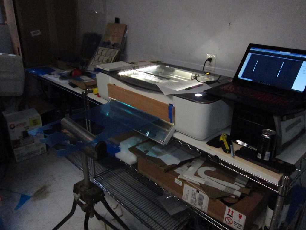
The final designs were too big to cut in my laser cutter (glowforge), so I had to break them into two pieces. The puzzle-piece line gives me two individual pieces to cut that can easily be put together again.
The animation has 15 frames, which meant 29 individual pieces to cut.
Cutting
I figured out what sizes of plexiglass I needed and bought the plexiglass from my local TAP plastics; it was about $90 worth. I didn’t want to spend a lot of time splitting pieces on my table saw, so I defeated the door interlock on my Glowforge for the larger pieces:
You really shouldn’t do this if you don’t have laser safety glasses designed for your particular laser’s frequency. In this case, I wore my normal safety glasses and closed off as much of the opening as possible; I now have a nice set of dedicated laser safety glasses. Don’t do this unless you understand the risks.
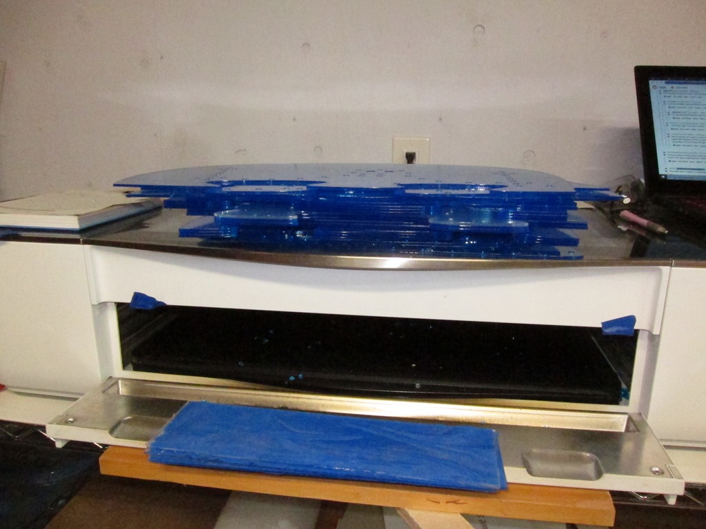
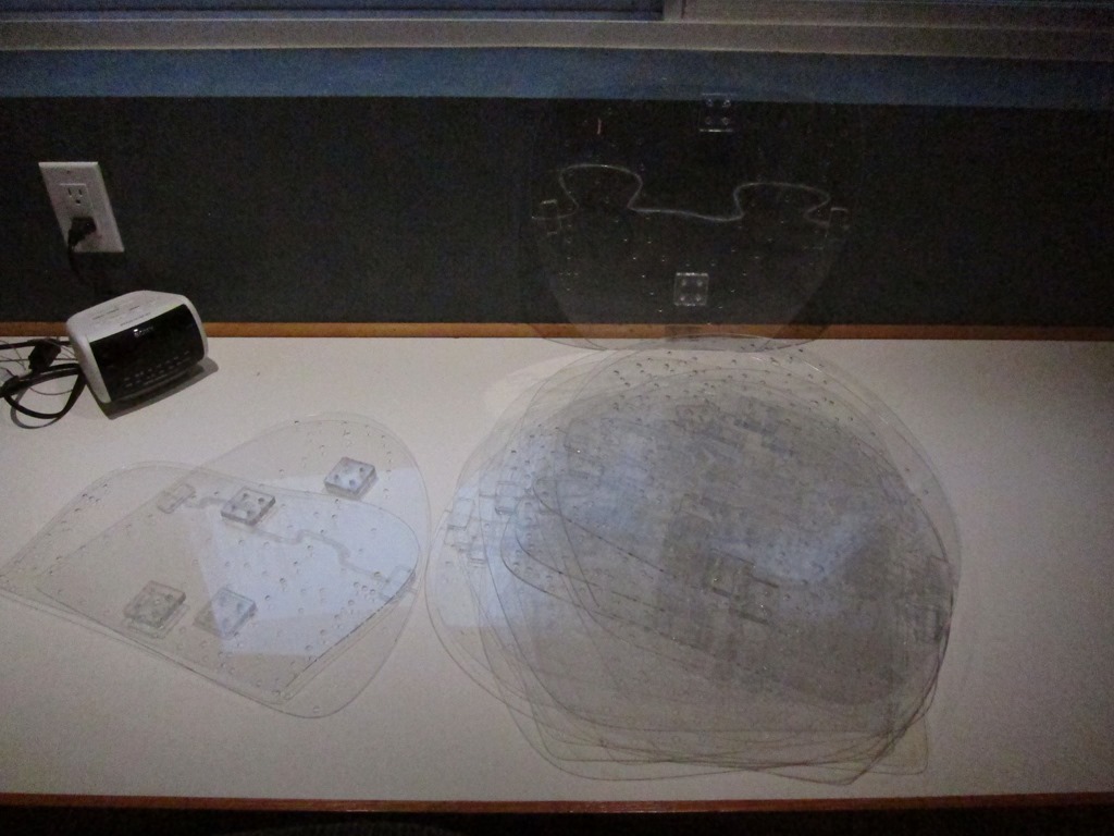
Here’s all the cut pieces stacked up:
This is a penguin prototype:
This was actually constructed earlier; it was used to determine size, and we decided to go about 25% larger. Thankfully, Fusion made this fairly easy to do.
Here’s the first production frame:
You can see the glue residue along the joining line. At the left and right sides there are short connectors that overlap the joint and provide much needed stiffening; they are on both sides. The squares with holes are spacers; the penguins will mount to wood supports and the spacers hold the wood away from the wiring that will be on the back. Zoom in to see the fine details.
Here’s the pile of penguins all glued together and ready for LEDs.
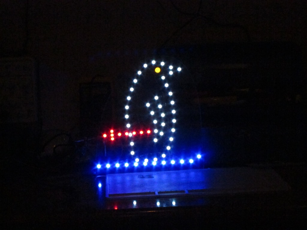
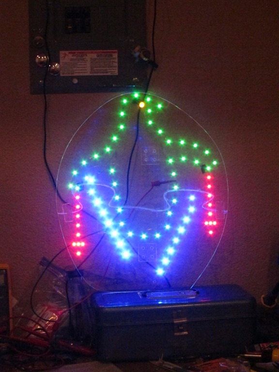
First light on the first frame:
Green was planned for the body outline rather than the white in the prototype but I didn’t have enough green LEDs at the time. The LEDs are brightness matched to look similar to human eyesight though the blues look too bright to the camera. Only 13 more to go!
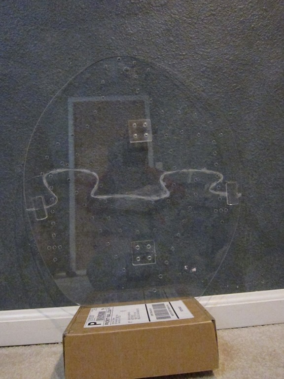
Here’s what the penguin looks like with the leds off:
Sorry about the messy and distracting background. For each section of LEDs, there are two sets of bare copper; one that is connected to 12V and one that is connected to ground. Leds are grouped based on their voltages; green and blue run in groups of 2 while reds run in groups of 4. At this point I realized that my ski poles had 9 leds which means that I had two groups of 4 and one individual LED, which was a pain. Each group has the appropriate resistor to set brightness. There are 70-odd LEDs in this frame, so figure something near to 200 solder joints.
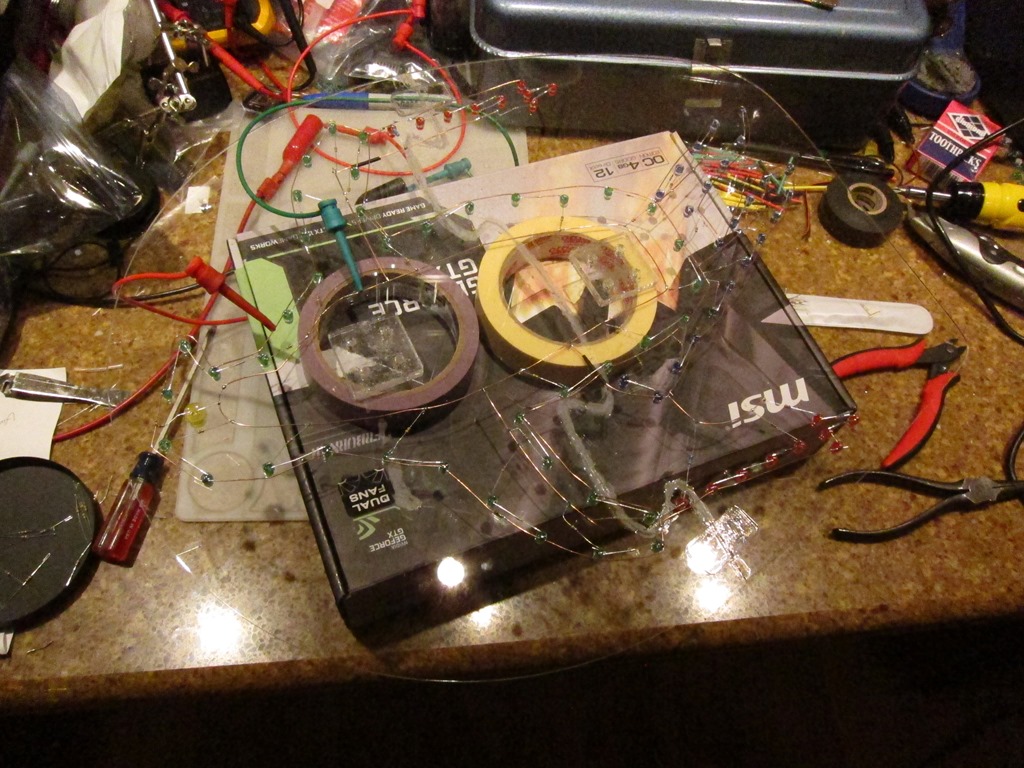
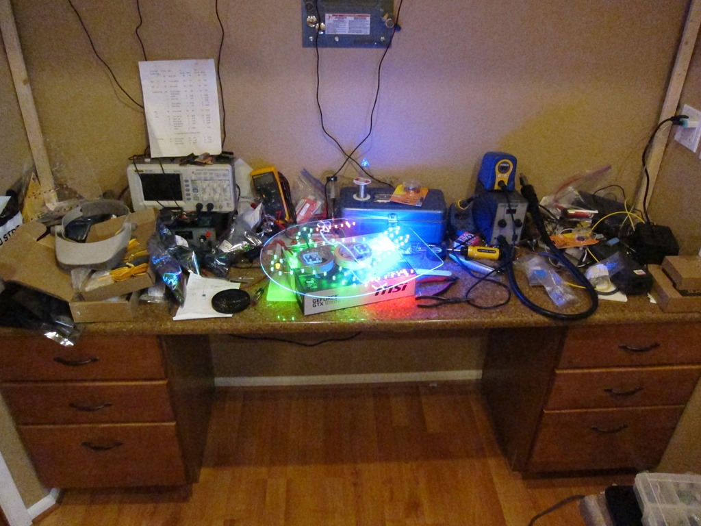
Here’s a picture of the workbench mess:
That’s not that bad except there is more mess here:
and here:
To waterproof all the wiring, I took the penguins outside and hit them very heavily with clear acrylic spray. I’ll know how well that worked when I take them down:
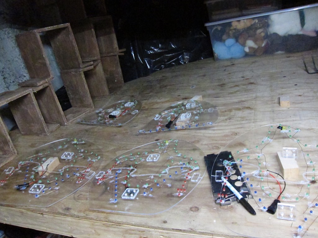
Here’s a view of them drying. They have waterproof power connectors attached and have frame numbers marked on them.
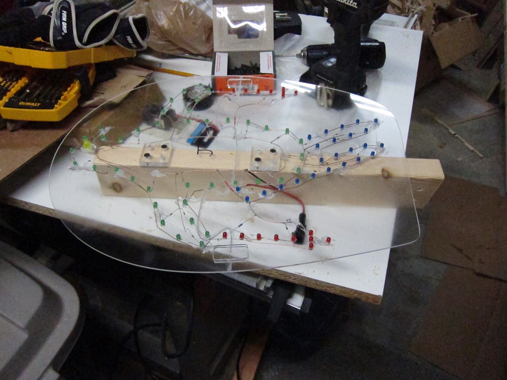
And then they were each mounted on short pieces of 2×3 wood which would have been painted if I had time; maybe I’ll do that when I pull them down after they have dried out. You can see the wiring quite well in this shot, and we can see that it’s frame “J”, or the 10th frame.
The next step was to build the wiring harness. I did a diagram of the expected layout in Visio:
From that, I went out into my driveway, took a couple of tape measures, and laid out what I needed. The controller was planned to be under the roof where “K” is, so I would run wire to that point and then leave an extra 10’. I unfortunately don’t have any pictures of this process; I was racing the weather.
Basically, I would start at “A” in the diagram, leave a couple of feet of slack cable, run it up to D, across the top, and then down to K and leave 10’ at that end. Each cable gets an adhesive label with the circuit letter at each end, and those will later be covered with clear packing tape to waterproof them. Continue the process with each cable all the way through K. The cable is 22-gauge alarm cable; I have used twinlead in the past and I have to say that this cable was a huge upgrade in terms of ease of use, and at $31 for 500’ is was pretty cheap. I did calculations on the voltage drop and decided that it wasn’t too bad (about 7% IIRC).
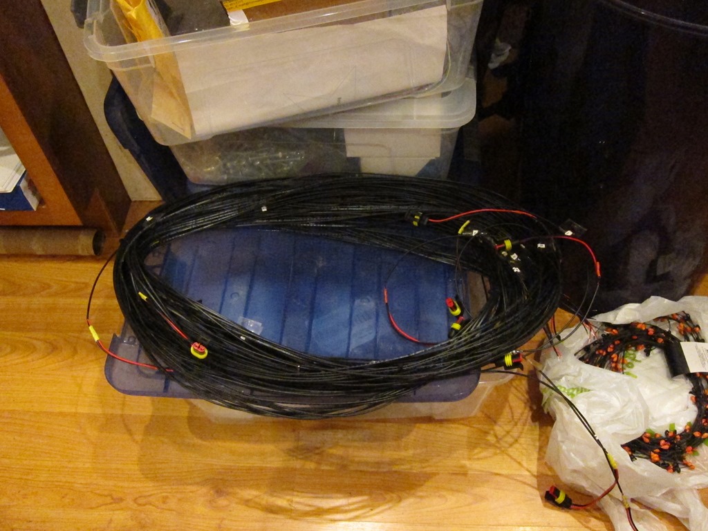
Once I had all the cables, they got bunded together with wire ties at every branching location and then additional wire ties to make the harness easy to handle. I got it all done just as the rain came down for real, and headed inside. Each penguin location got the other half of the waterproof connector soldered on and then covered in heatshrink tubuing, and the controller ends got stripped to be connected to the controller. Here’s the final roof harness:
The penguins got installed on the roof with various arrangements of wood to support them and were plugged into the harness. I then spent a day or two figuring out how to do the penguins in front of the house; they are supported on 1/2” metal EMT tubing. I also created a separate harness for those penguins (one in the air, one crashed in the tree, and then a small one where the one in the tree lost his poles and skis) using the same process.
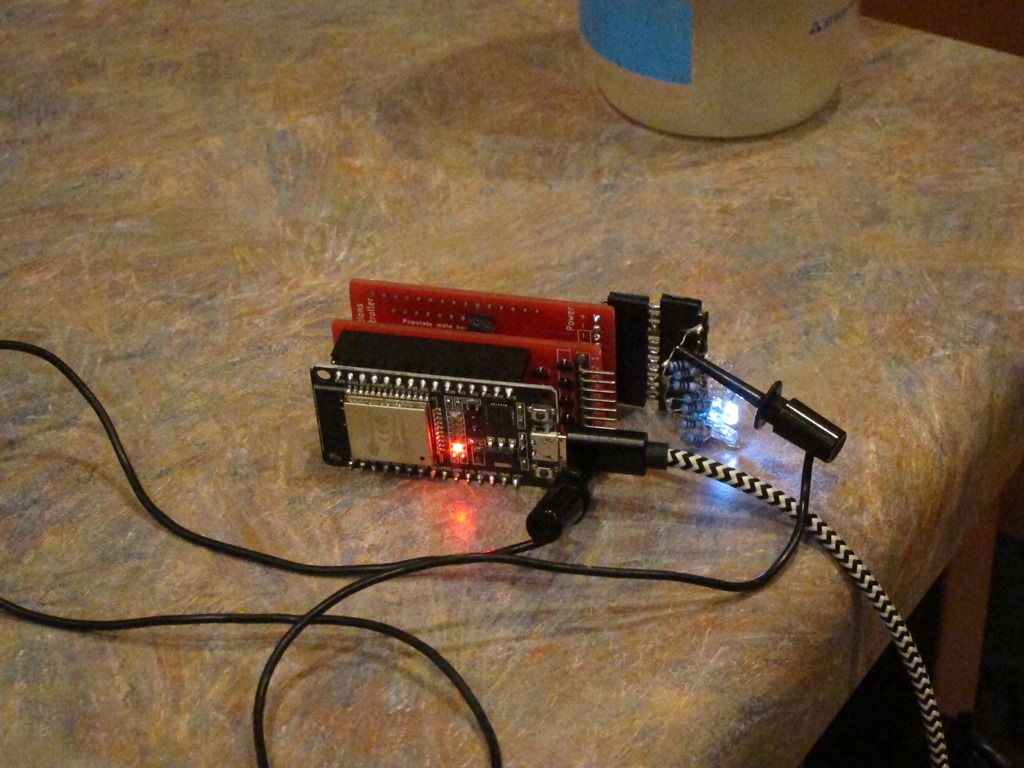
I finished building the controller:
Nearest to us is the ESP32 controller board that runs the animation software, and behind it are two custom 8-channel MOSFET switching boards. Attached to the back MOSFET board is a series of LEDs used for debugging.
The ESP runs custom software that drives the ESP32’s 16-channel PWM hardware. The ESP32 is ridiculously full-featured for the price. One of my goals for the project was to *not* have to pull the controllers out of their installed location to update the animation, so I created a really rudimentary web-based IDE and an animation language:
This is the current active view from the ESP running the penguins as I sit here and write. The left textbox shows the code and the right one shows errors if there are any. I wrote the animation outline and programmed it in, and then took my laptop to the garage and we’d watch the animation and I’d tweak it as necessary, it took us about 10 minutes to get what we wanted, and I would have spent more than that on a single iteration of “unplug the controller, take it downstairs, plug it in, modify the software, compile it, upload a new version, take it outside, plug it back in, and see if it worked”. That worked very well.
I’m calling the language “Dim”, because it’s good at dimming things and not very smart. In the code “DI” means drive a specific channel to a specific brightness over a specific cycle count (each cycle is about 10mS, so it runs at 100 Hz), and D lets you specify more than one operation to occur at once during the following “A” (animate) command. The language does have for loops but is desperately in need of functions/methods for this usage; I have those in a newer version.
Here’s a bit of code running on a second instance of the controller that flashes 5 of the ornaments I make in a random pattern:
channel=2
FOR count 1:100
D(50, channel, 0)
channel=R(1:6)
DI(30, channel, 1)
ENDFOR
That took about 5 minutes to write.
Finally, here’s a daytime tour of the installation which shows the penguins mounted on the roof and in front of the garage and the controller board with terminal strips.


