Browsing posts in: Glowforge

French Cleat Electronics Workbench…

IMG_9709

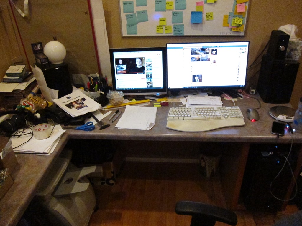
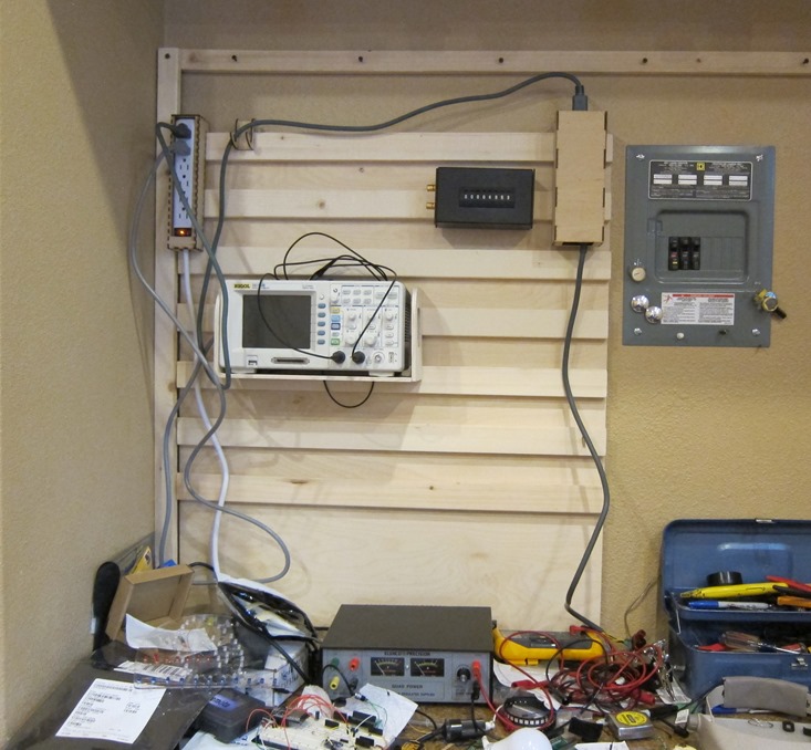
I’m not known for the cleanliness of my workspaces; my office desk is a mess right now, my garage workbench is a mess, as are my other workbenches.

But my electronics one is messy enough to be problematic, and the root problem is that there’s just too much stuff one the workbench; power supply, oscilloscope, toolbox, solder station, hot air rework station all take up a lot of space, and the work surface doesn’t have lot of depth, so I end up with a small clear workspace even without clutter.

A while back I was looking at my Rigol scope, and thought that I might have more room if I could mount it on the wall. And that obliquely led me to the current project.

FH18MAY_586_00_006-french-cleat-tool-wall-featured

I’ve been watching some woodworking on YouTube, and that led me to a series on french cleat walls. They are pretty popular for woodworking shops as they keep all of their tools handy. Looking at my garage space – where I do some woodworking-adjacent projects – I don’t have a lot of wall room for one of these, and most of projects I do occur elsewhere, so I wanted to keep my tools in their boxes. Not a great solution there.

But that triggered a thought about my electronics space; I don’t move my tools around and I could use the organization.

So I went looking in my garage and found that I had some leftover 12mm baltic birch plywood from another project, and I acquired some 2×3 pine for the cleats.

Making the cleat wall is pretty simple; you just cut your cleats wood at a 45 degree angle and then attach it to the plywood using a regular spacing. If you want details, here’s a video I did of the process:


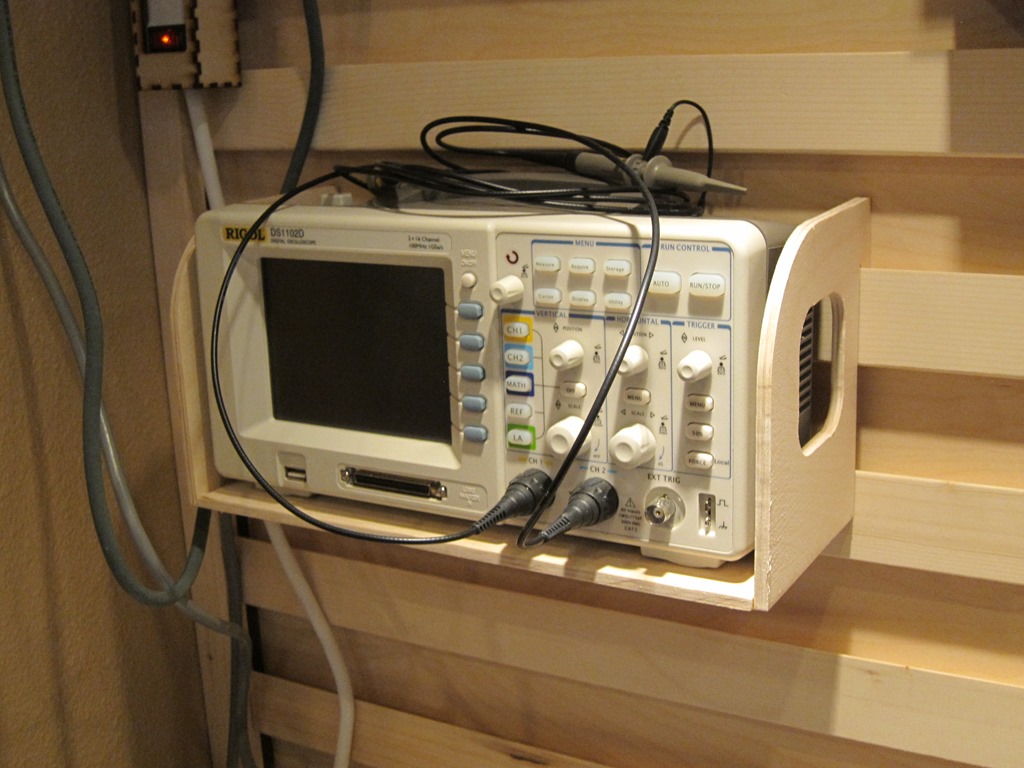
I took the wall down to my workbench and attached it to the wall. Then it was time to start figuring out how to attach items to the wall; this is generally some sort of shelf or box with the mounting tabs that hook onto the cleat. First up was the oscilloscope, partly because it was big and partly because it was straightforward to design.

Oscilloscope Shelf

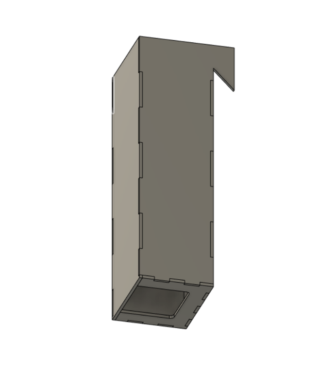
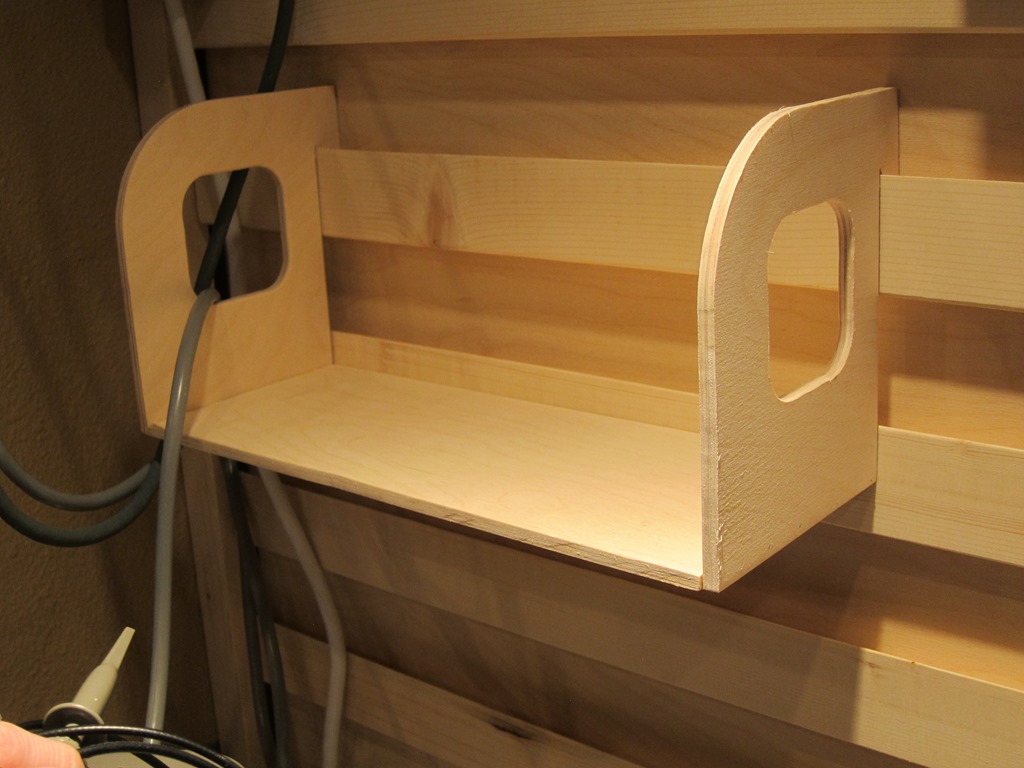
It’s simple enough that I could have just created a mock-up in cardboard and then used that to create the actual version, but I wanted to play a little, so I did a full CAD design. It was a pretty quick design in Fusion 360 and I’d show you a nice rendered version, but somehow it didn’t get saved along the way. Here’s what the side panel of the shelf looks like; the hole in the end is for the power cord at one end and the cooling fan at the other, and the left part hangs off the cleat:

Pro tip: The 1x stock you buy may not be exactly 3/4” thick; mine was 11/16” instead. So measure it first; for this shelf I had do sand down the back edge of the cleat.

image

The bottom shelf is just that, a rectangular piece of wood between the end pieces.

As a material I used some 1/4” baltic birch (probably 6mm actually), and I decided to use my Shaper Origin to make the shelf. It is held together with wood glue and some very thin wire pins shot in witn my pin nailer. Here’s the video if you want the details:

The result is nice and pretty, though I didn’t sweat trying to get things perfect; it’s not furniture:

IMG_9714

IMG_9715

Because of the way the cleats are designed, gravity pulls the mounting cleat both against the wall cleat and the wall plywood, and the back of the shelf presses against the second cleat. It’s surprisingly secure and yet very easy to move around.

About the time I was finishing this, I said to myself, “Self, that was fun and you made a lot of sawdust, but there’s nothing in that design that you couldn’t have done much quicker and easier with your laser cutter, so at this point I switched tools.

XBox 360 Power supply box

When I added a heated bed to my 3D printer, I bought an XBox 360 power supply to power it, and I found that they are wonderful for powering 12V loads; the ones I have provide up to 16 amps of power. So I bought a second one from Goodwill for $4.95 and have used it when I need a hefty supply for testing (like my WS2811 expander which I stress test with 3 50-watt 12v light bulbs). Cheap, compact, and lots of cheap power – what’s not to like.

Well, I don’t like that it’s cluttering up my workbench, so I’m going to build a box for it.

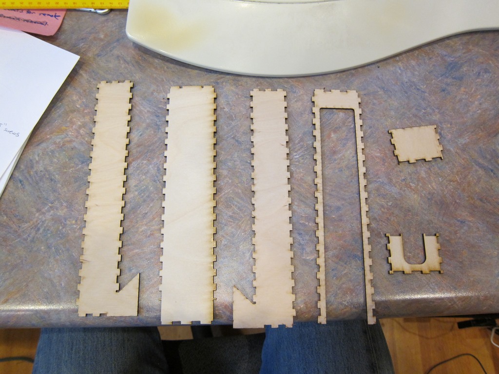
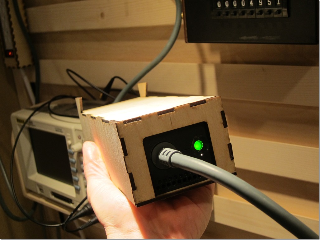
Here’s the CAD design, the laser-cut parts, and the final result. It’s cut out of 0.10” (2.5mm?) plywood that is strong and easy to cut on the laser (mine’s a GlowForge) and then glued together with wood glue.

image

IMG_9707

IMG_9711

I measured the power supply with my calipers and it ended up just on the tight side; the power supply slides in but barely. The big cutout for the close end is because there are air holes there.

The other end of the cable currently just has a set of speaker terminals that accept banana plugs and the enable wires soldered together so it’s always on. Sometimes in the future, that cables going to terminate in a power-supply box with an on off switch.

The xbox power supply hangs up high. And now I need a place to plug it in as the cord isn’t long enough to reach to the outlet under the workbench.

Power strip box

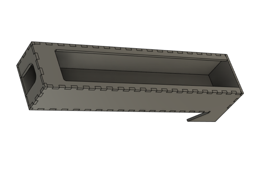
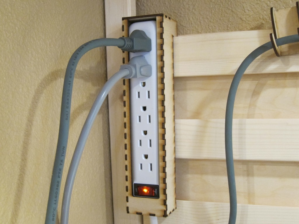
Another simple box, with the dimensions defined by the size of the power strip that I wanted to use. The design is quite simple with a bit of an assembly caveat; the box has both a top and a bottom so you have to assemble it around the power strip.

image

IMG_9713

Resistor decade box

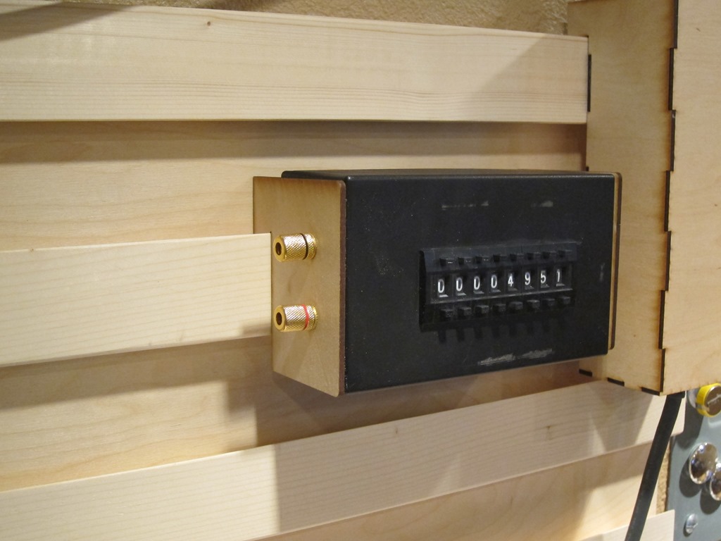
I built the decade box a few years ago based on this instructable. I do a fair bit of work with LEDs and I often find myself wanting to pick an LED value based either on measured current or brightness. I used to do that with a potentiometer, but it’s much easier to use a decade box.

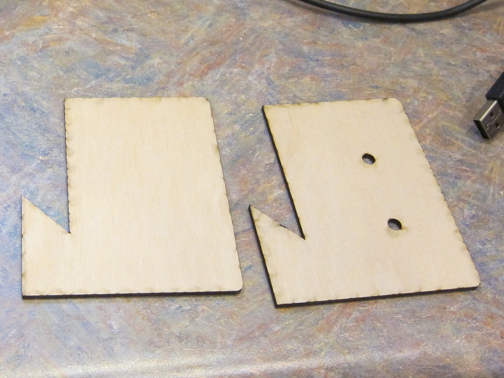
The design here just has two end hangers; one end is attached using the output posts for the decade box, and the other one is just hot-glued on.

IMG_9708

IMG_9710

You might notice there are some smoke marks on the wood; if I wanted nice I would have masked them off but that was more work than I wanted for this.

Wire hanger

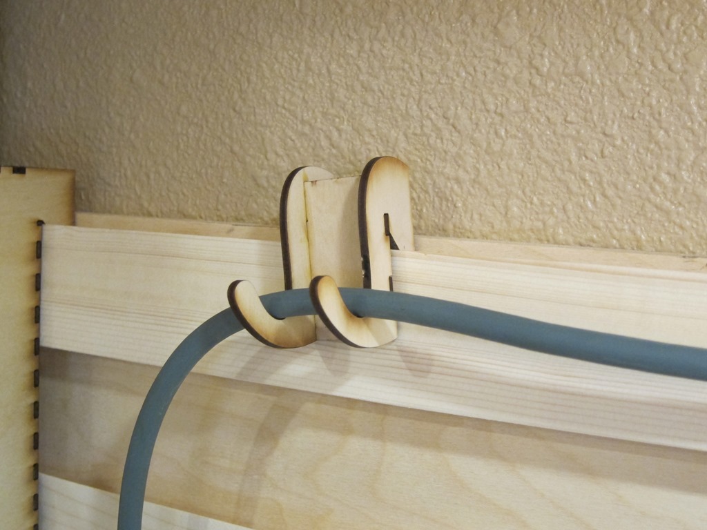
Just one more design for the first wave; I knew I would have wires running across the board and wanted a way to support them:

IMG_9712

A simple three-piece design hold up a power cord. It’s tilted because of the weight of the cord is heavier on one side; I’ll probably do a version with a single hanger in the middle. Or I might cut some one-piece hangers out of 1/4” plywood.

Video tour

If you would prefer a video tour of the completed items, you can find it here:


Power supply hanger
Model 1627A Right

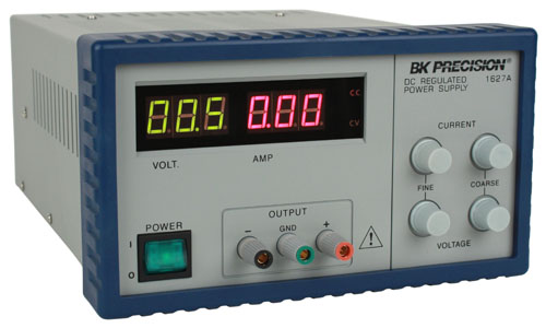
When looking at some of the small Chinese power supplies that are out there, I got a line on a nice surplus BK Precision 1627A on Ebay for $55 and ended up buying that instead. I have an older 4 voltage power supply (+12V, –12V, 5V, and adjustable) that I’ve used quite a bit, but it’s pretty rare that I need multiple voltages these days, I already have the hefty 12V, and I’m going to be adding some dedicated 5V supplies as well. I haven’t used +/- power supplies in a long time, so I think the old supply is going to get packed away for now.

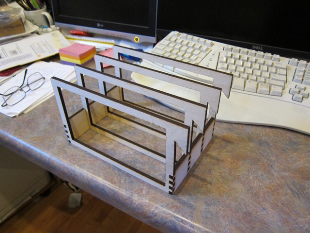
To do a hanger for this looked a bit more challenging than my previous hangers because this is bigger and it weighs 16 pounds. I did the design and cut it out of 1/4” plywood:

IMG_9716

The frames here are about 10” x 7” in size. They are cut out of 1/4” (probably 6mm, actually) and glued together.

Pro tip: Go back and look at the picture of the power supply picture above. If you look closely on the side and the talk, you will see some screws sticking out. If you measure precisely and cut to that precise measurement, the pretty holder you create will *not* fit over those screws, and you’ll need to remove the screws – and maybe the equipment feet – to get the frames to fit over the item (the power supply in this case).

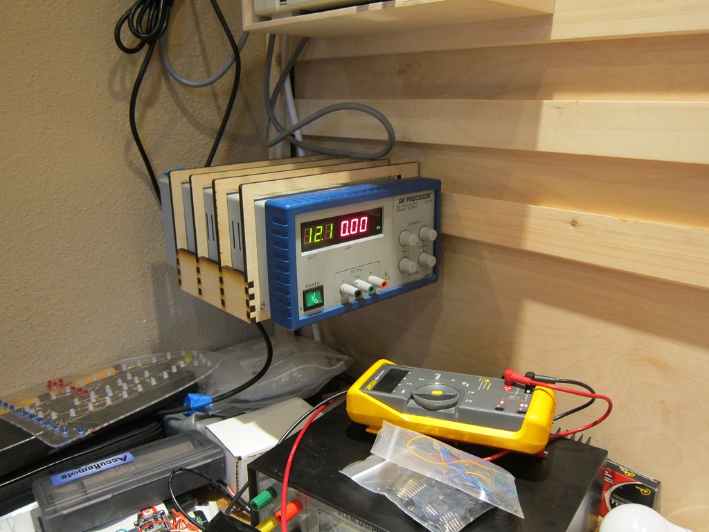
Not only did I do that, but the first time I put the hanger on I had it on the wrong side, so I had to repeat it. But I did get to the final result:

IMG_9717

Futures

One of my goals was to get my Fluke multimeter off my desk and up in the air, but there are some issues, the biggest one being that the digits are in shadow if the meter is vertical against the wall. I’ve had some designs that put it at the same angle the stand in the base does, some designs that let you modify the angle, and another idea that I might just add some white LEDs to the side so it could be vertical.

There will be a power supply station close at hand; I think it’s going to support 12V from the xbox supply, 5V both on banana plugs and on multiple USB plugs, and I might integrate one of the cheap chinese boost/buck supplies to give options.

Finally, there’s the right side of the bench, which has my soldering iron base and my cheap chinese hot-air rework station. I may end up with a cleat wall on that side I can get them up as well.



Skiing penguins build log retrospective

My skiing penguins project has been up and animating for a few weeks, and I thought I’d write down the process for others so that they can learn from what I did. And also so I can remember what I did and why. There are some other blog posts that talk about some of the specifics for the sequence controller I built.

First off, there’s a video here that shows the final result.

The my initial idea was to do something with LEDs and single frame animation; see some of the animations that were done at ZooLights at Pt. Defiance many years ago was what got me into this hobby. I had a big garage roof that was unutilized, and after some discussion with my wife we decided that skiing penguins was a good place to start.

CAD

 I started looking around for online penguin designs to use as a starting point and found a couple. Then I started up Fusion 360 and created a new project.

I design (and sell) LED ornament kits, so I’m used to doing these designs. Here’s a video that shows the technique that I use to space the LEDs out evenly along an outline; that is what I used for all of the penguins. Here’s a in-process look at one of the designs:

image

and a final one:

image

The final designs were too big to cut in my laser cutter (glowforge), so I had to break them into two pieces. The puzzle-piece line gives me two individual pieces to cut that can easily be put together again.

The animation has 15 frames, which meant 29 individual pieces to cut.

Cutting

I figured out what sizes of plexiglass I needed and bought the plexiglass from my local TAP plastics; it was about $90 worth. I didn’t want to spend a lot of time splitting pieces on my table saw, so I defeated the door interlock on my Glowforge for the larger pieces:

IMG_9644

You really shouldn’t do this if you don’t have laser safety glasses designed for your particular laser’s frequency. In this case, I wore my normal safety glasses and closed off as much of the opening as possible; I now have a nice set of dedicated laser safety glasses. Don’t do this unless you understand the risks.

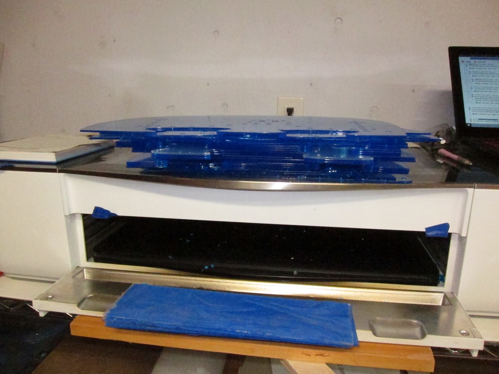
Here’s all the cut pieces stacked up:

IMG_9647

This is a penguin prototype:

IMG_9651

This was actually constructed earlier; it was used to determine size, and we decided to go about 25% larger. Thankfully, Fusion made this fairly easy to do.

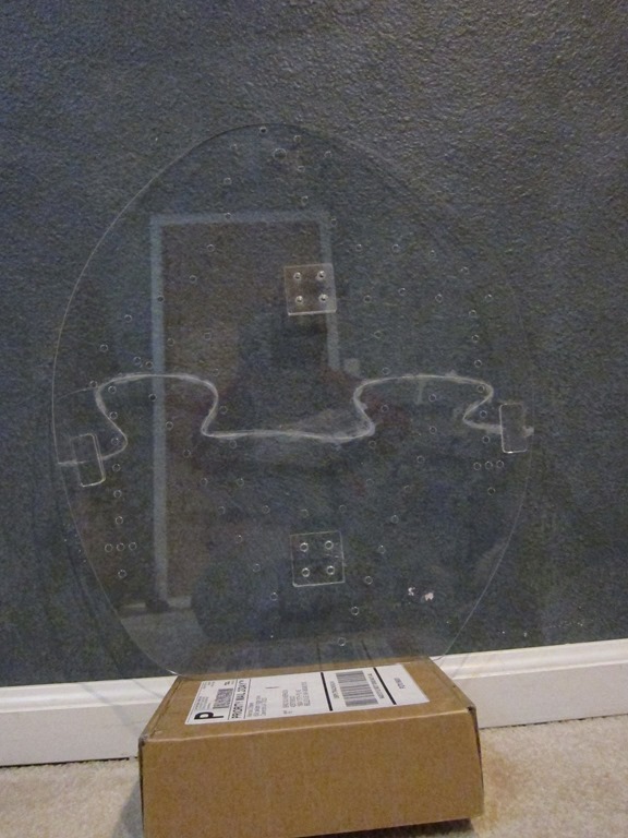
Here’s the first production frame:

IMG_9654

You can see the glue residue along the joining line. At the left and right sides there are short connectors that overlap the joint and provide much needed stiffening; they are on both sides. The squares with holes are spacers; the penguins will mount to wood supports and the spacers hold the wood away from the wiring that will be on the back. Zoom in to see the fine details.

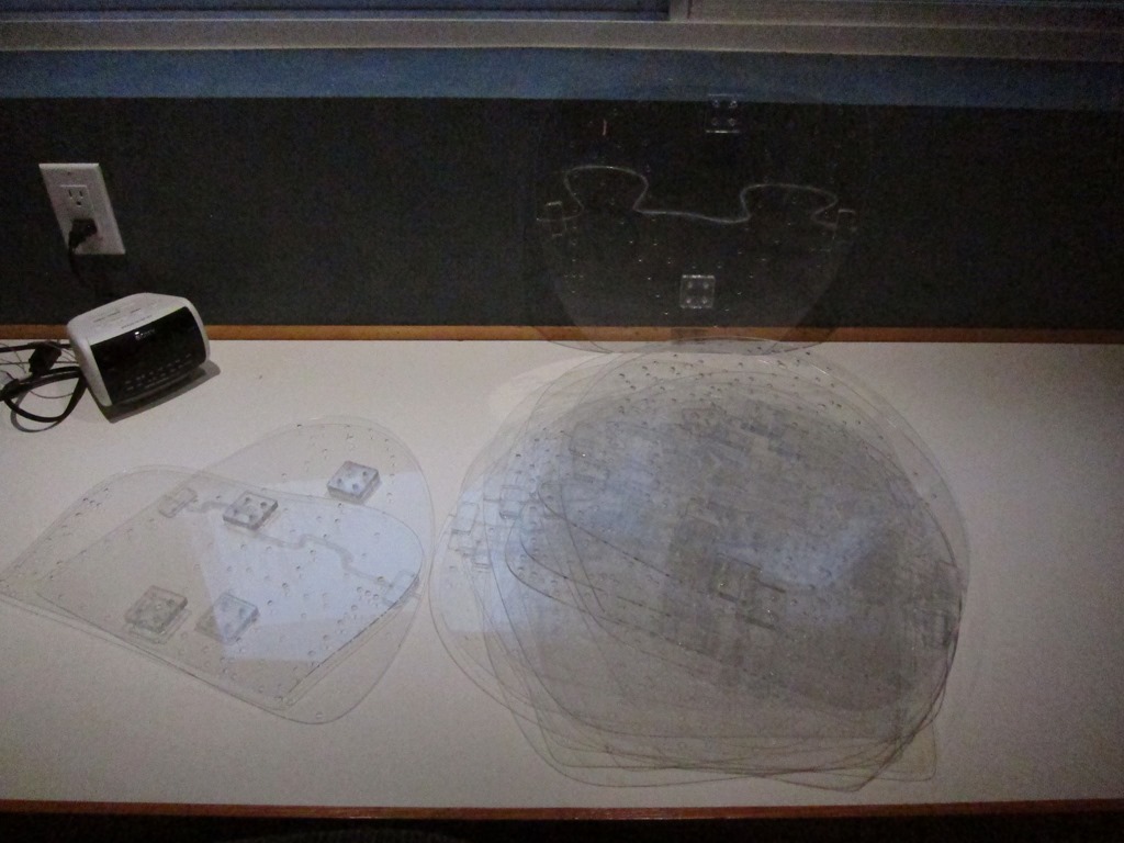
Here’s the pile of penguins all glued together and ready for LEDs.

IMG_9656

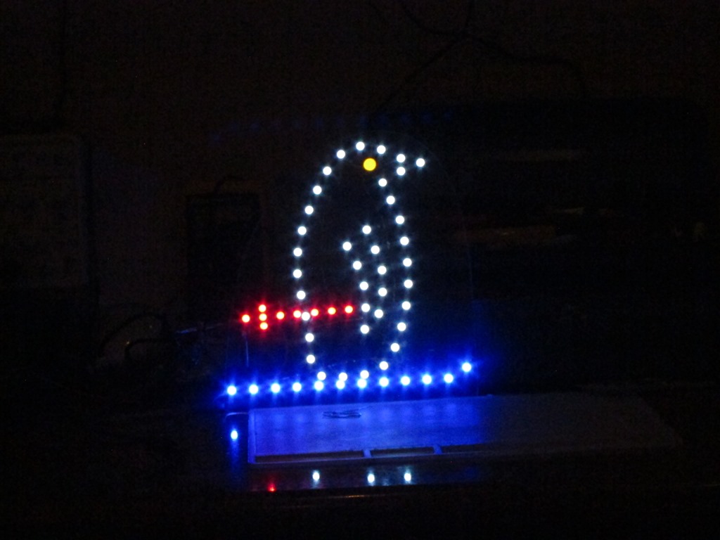
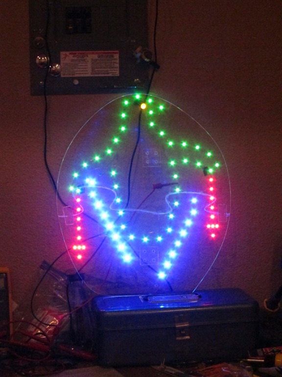
First light on the first frame:

IMG_9659

Green was planned for the body outline rather than the white in the prototype but I didn’t have enough green LEDs at the time. The LEDs are brightness matched to look similar to human eyesight though the blues look too bright to the camera. Only 13 more to go!

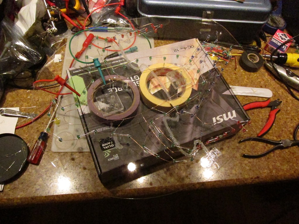
Here’s what the penguin looks like with the leds off:

IMG_9660

Sorry about the messy and distracting background. For each section of LEDs, there are two sets of bare copper; one that is connected to 12V and one that is connected to ground. Leds are grouped based on their voltages; green and blue run in groups of 2 while reds run in groups of 4. At this point I realized that my ski poles had 9 leds which means that I had two groups of 4 and one individual LED, which was a pain. Each group has the appropriate resistor to set brightness. There are 70-odd LEDs in this frame, so figure something near to 200 solder joints.

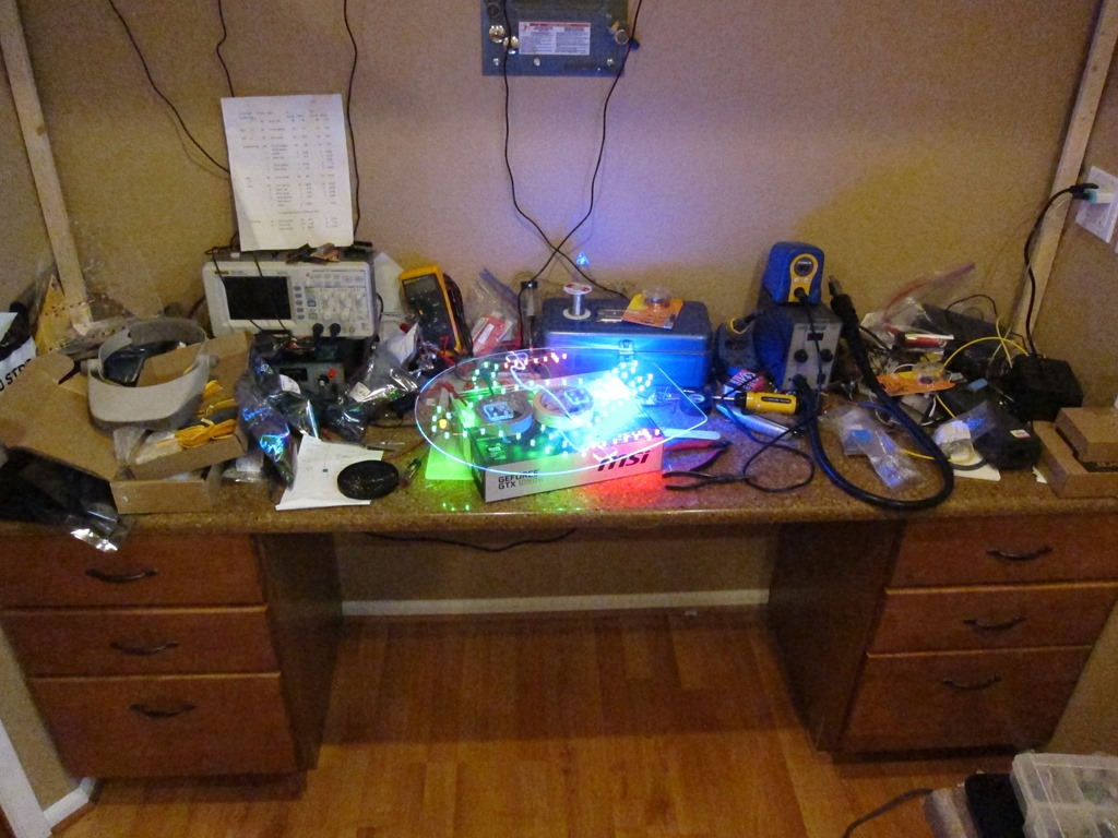
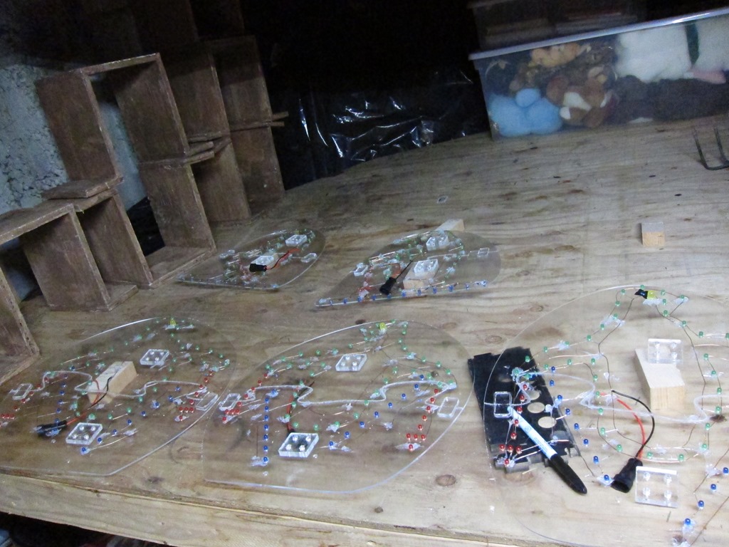
Here’s a picture of the workbench mess:

IMG_9662

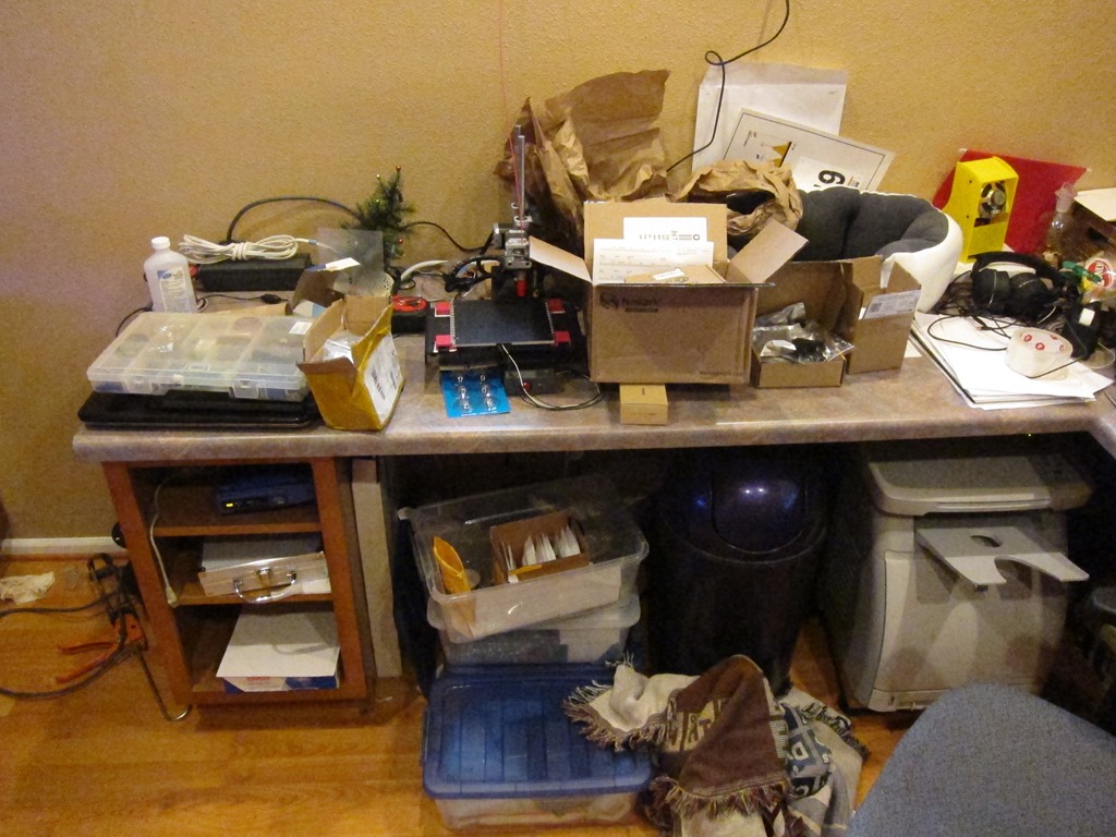
That’s not that bad except there is more mess here:

IMG_9663

and here:

IMG_9664

To waterproof all the wiring, I took the penguins outside and hit them very heavily with clear acrylic spray. I’ll know how well that worked when I take them down:

IMG_9665

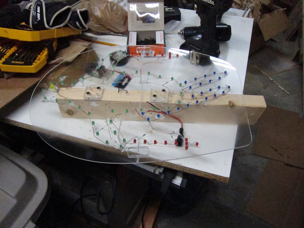
Here’s a view of them drying. They have waterproof power connectors attached and have frame numbers marked on them.

And then they were each mounted on short pieces of 2×3 wood which would have been painted if I had time; maybe I’ll do that when I pull them down after they have dried out. You can see the wiring quite well in this shot, and we can see that it’s frame “J”, or the 10th frame.

IMG_9670

The next step was to build the wiring harness. I did a diagram of the expected layout in Visio:

image

From that, I went out into my driveway, took a couple of tape measures, and laid out what I needed. The controller was planned to be under the roof where “K” is, so I would run wire to that point and then leave an extra 10’. I unfortunately don’t have any pictures of this process; I was racing the weather.

Basically, I would start at “A” in the diagram, leave a couple of feet of slack cable, run it up to D, across the top, and then down to K and leave 10’ at that end. Each cable gets an adhesive label with the circuit letter at each end, and those will later be covered with clear packing tape to waterproof them. Continue the process with each cable all the way through K. The cable is 22-gauge alarm cable; I have used twinlead in the past and I have to say that this cable was a huge upgrade in terms of ease of use, and at $31 for 500’ is was pretty cheap. I did calculations on the voltage drop and decided that it wasn’t too bad (about 7% IIRC).

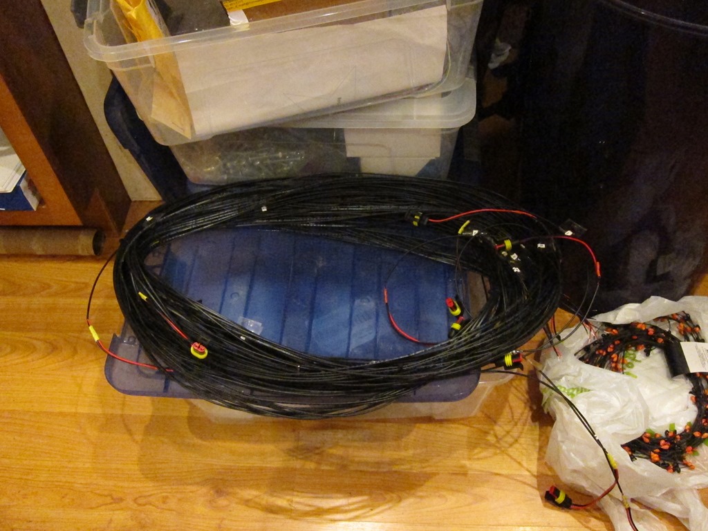
Once I had all the cables, they got bunded together with wire ties at every branching location and then additional wire ties to make the harness easy to handle. I got it all done just as the rain came down for real, and headed inside. Each penguin location got the other half of the waterproof connector soldered on and then covered in heatshrink tubuing, and the controller ends got stripped to be connected to the controller. Here’s the final roof harness:

 IMG_9671

The penguins got installed on the roof with various arrangements of wood to support them and were plugged into the harness. I then spent a day or two figuring out how to do the penguins in front of the house; they are supported on 1/2” metal EMT tubing. I also created a separate harness for those penguins (one in the air, one crashed in the tree, and then a small one where the one in the tree lost his poles and skis) using the same process.

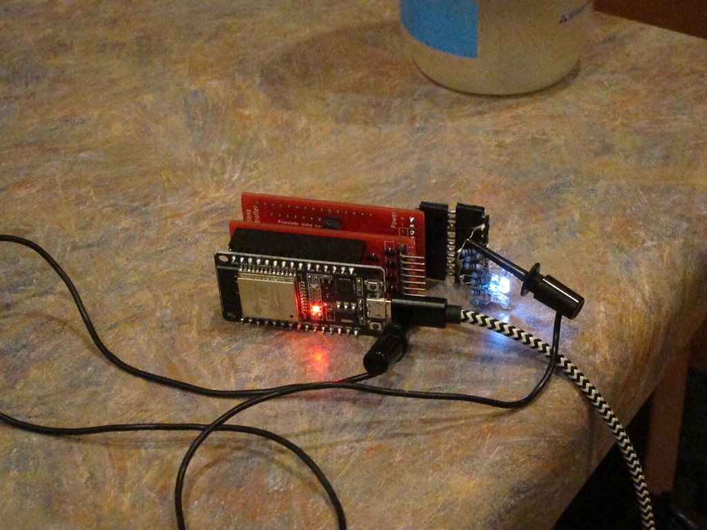
I finished building the controller:

IMG_9672

Nearest to us is the ESP32 controller board that runs the animation software, and behind it are two custom 8-channel MOSFET switching boards. Attached to the back MOSFET board is a series of LEDs used for debugging.

The ESP runs custom software that drives the ESP32’s 16-channel PWM hardware. The ESP32 is ridiculously full-featured for the price. One of my goals for the project was to *not* have to pull the controllers out of their installed location to update the animation, so I created a really rudimentary web-based IDE and an animation language:

image

This is the current active view from the ESP running the penguins as I sit here and write. The left textbox shows the code and the right one shows errors if there are any. I wrote the animation outline and programmed it in, and then took my laptop to the garage and we’d watch the animation and I’d tweak it as necessary, it took us about 10 minutes to get what we wanted, and I would have spent more than that on a single iteration of “unplug the controller, take it downstairs, plug it in, modify the software, compile it, upload a new version, take it outside, plug it back in, and see if it worked”. That worked very well.

I’m calling the language “Dim”, because it’s good at dimming things and not very smart. In the code “DI” means drive a specific channel to a specific brightness over a specific cycle count (each cycle is about 10mS, so it runs at 100 Hz), and D lets you specify more than one operation to occur at once during the following “A” (animate) command. The language does have for loops but is desperately in need of functions/methods for this usage; I have those in a newer version.

Here’s a bit of code running on a second instance of the controller that flashes 5 of the ornaments I make in a random pattern:

channel=2
FOR count 1:100
   D(50, channel, 0)
   channel=R(1:6)
   DI(30, channel, 1)
ENDFOR  
      

That took about 5 minutes to write.

Finally, here’s a daytime tour of the installation which shows the penguins mounted on the roof and in front of the garage and the controller board with terminal strips.


Cat bed elevation device

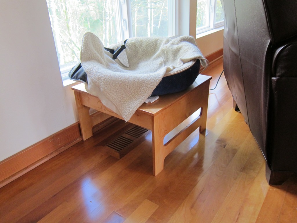
We have a couple of heated for out cat to hang out in, which she really likes. One of them lives in the living room near the windows, but unfortunately if she is in the bed she can’t see out the windows.

What was needed was a way to elevate her so that she could see out. Which seemed like a perfect opportunity for some CAD and CNC.

The design

I fired up Fusion 360 and started playing around. I started with the basic dimensions; the top would be 18” square (the bed is really pretty big) and it needed to be 11 inches tall. Then it was off to build the basic model.
In the past, I’ve used “through tabs” which are easy to do but not aesthetically pleasing. In this design, none of the tabs go all the way through, which makes it a lot nicer looking.
After a couple of hours I had the basic design:

image

The bottom cutouts on the ends are so that there are four discrete legs for support, and the holes are to make it look a little more interesting. I played around with another slot farther up, but decided not to for reasons that will later become apparent. Note that there are no visible tabs.

Here’s the inside of one of the ends:

image

This shows the cutouts that I will make for the end; there is the outline and slot that go all the way through, the recessed pockets for the tabs from the sides, and then the tabs that will go into the pockets cut into the top.

There are “dogbones” cut at the corners; these are needed so that the rectangular corner of the tab has someplace to go. This is using the new “minimal dogbone” add-in for Fusion 360, which is a great improvement over the previous version.

Material

I went to my lumberyard (Dunn Lumber) and procured a sheet of 12mm baltic birch plywood for $30. It comes in an exceedingly inconvenient 5’x5’ size, which means that I cannot fit it in the back of my pickup. I can, however, tie it to the top of my outback.

Cutting

I trimmed the 5×5 sheet into a 2×5 sheet for this project and a 3×5 sheet for later projects, and then set up my workspace. It’s a melamine shelf with some thin sacrificial sheets of 1/8” MDF on top and then the actual wood clamped on top.

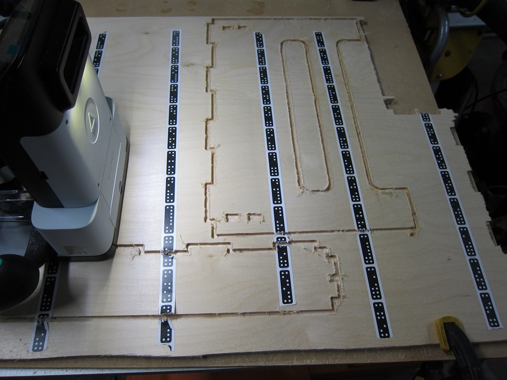
Shaper suggests that you use double-sided tape to hold the wood down, which is a really good idea that I keep forgetting to do. I added the domino tape so the shaper can figure out where it is, and started cutting.

It takes multiple passes to go through 12mm stock, and after a few options I settled on 5mm, 10mm (the depth of the pockets), and 12.3 mm to cut through.

Here’s a shot partway through the cutting:

IMG_9366

I took that picture because the Shaper crashed in the middle of the cut. It luckily remembers the layout so you can keep cutting when you startup, but you sometimes lose tracking before it finishes retracting the bit so there are small mistakes in the cuts.

I had about 8 crashes while cutting the parts for this. Unlike previous projects – where it would crash only while cutting and in reproducible situations – these crashes seemed to be much more random. I’m working with Shaper on it but haven’t figured anything out yet; in this case it cut flawlessly for about 45 minutes before any issues showed up, so I suspect it’s heat related.

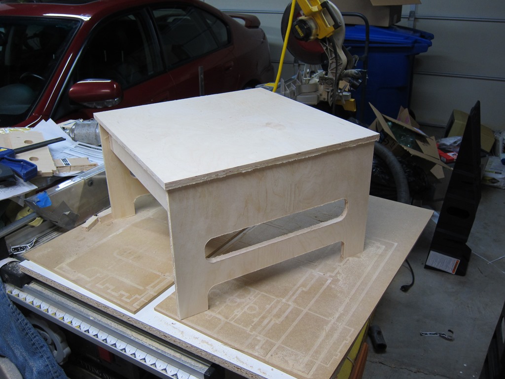
Anyway, eventually the last part was cut, and I could fit the pieces together. One of the joys of the CAD-based approach is that if you don’t make mistakes, things just fit together. I used my soft-blow hammer and ended up with this:

IMG_9371

Definitely looks like a stool. You can still see a lot of fuzz that needs to be cleaned up and an overall sanding is in order.

It was at this point I realized that I messed and hid the nice surface of the plywood up instead of down, which means the display faces have a number of patches that should have been on the inside.

Sigh. Well, my cat won’t mind.

I spent a lot of time sanding and de-fuzzing the project, and it seemed like things were okay.

Identification

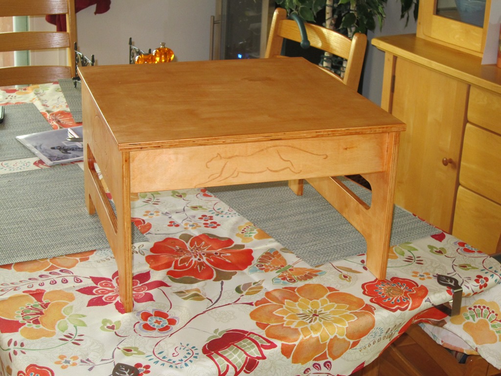
As you can see, it’s definitely a stool, but it’s not a definitely a cat stool. It needed something so that our cat would know that it was her.

After spending approximately 20 hours looking at cat drawings online, I came across a set that were very minimalist, and I picked four, two for the ends and one for each side.

Those got cleaned up an image editor and then engraved into the wood with my GlowForge. That took about 45 minutes.

Assembly

The sides were glued together, assembled temporarily into the top for alignment, and clamped until they were dry. Then this was repeated to glue the sides to the top.

Finishing

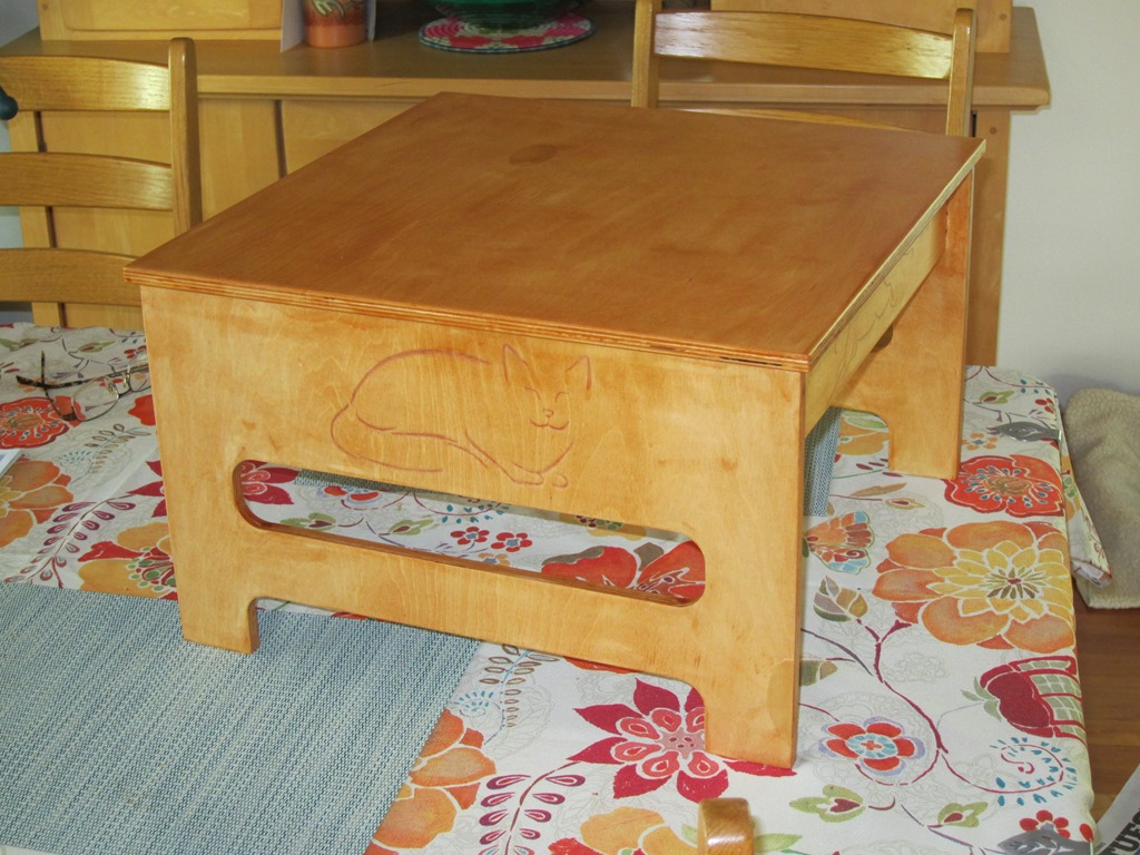
I wanted something a little more golden than the natural color, so I wanted a bit of stain. I decided to kill two birds with one stone and get a polyurethane with stain.

Bad idea. Maybe a good idea if you are spraying the finish, but applying by hand every slight difference in thickness shows up as a difference in color, and if you get any runs they look pretty bad.

Lesson learned for later. After the first coat dried, everything got sanded with steel wool to knock down the raised grain, and a second coat finished it off.

IMG_9377IMG_9376

And an action photo:

IMG_9378

As I have not obtained a model release from the cat I am contractually unable to show photos of her in the bed.

Shaper project is here.


DLE (Globes of Fire) Part 5 – First Board!

When a new telescope is completed, one of the big milestones is known as “first light” – the first time that the telescope is used as it is intended.

Now that I am the proud owner of a reflow oven – a modified Black & Decker toaster oven fitted with Whizoo’s Controleo3 reflow oven kit – and I have a new version of my boards back – it’s time to think about how to build these things in a reasonable way.

The plan is obviously to switch from hand-soldering to reflow. To do that, the first thing that I need is a stencil that I can use to apply solder paste. Thankfully, kicad makes this really easy; you can modify the solder pad tolerances in the program, and the pcb editor can write out SVG files (thanks to Rheingold Heavy for this post). If I have the pads, I can easily cut a stencil, likely out of mylar because it’s a bit cheaper than Kapton is.

That would give me a way to do a single board if I could hand-align it closely enough. But each of the globes needs 12 of these boards, and hand-aligning is a pain.

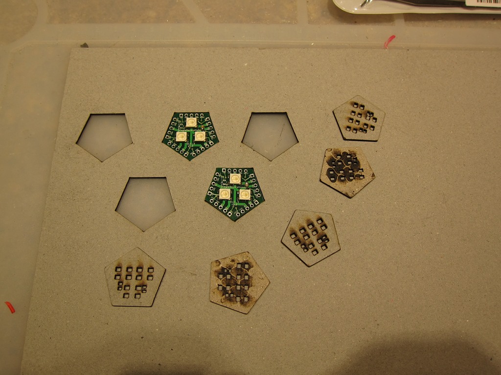
So… what my real plan to do is to cut holes in a piece of hardboard (or cardboard) that will hold a number of the boards (12 or 24) and then a matching stencil. If I align the stencil one, then I can put solder paste on all of them.

IMG_9223

So, here’s the test. I took the pad svg and the board edge svg, joined them in inkscape and then cut them on the glowforge. As you can see, the boards fit perfectly into the cutouts, and the solder pads cut correctly. Next I will need to do a better version of this, with different colors for the pads and board edge so I can turn them off and off when laser cutting. I’m also probably going to cut holes for some posts that will give me registration between the board with cutouts and the stencil.

You can also see the first two boards that ran through the reflow oven. I did the solder paste without a stencil and I also skipped baking the LEDs since they showed up in a factory-sealed pack and have been sealed since, and both boards came out fine. And a 10 minute reflow cycle is a lot quicker than hand soldering…


An inexpensive glowforge stand…

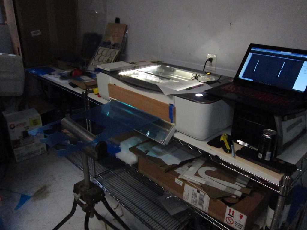
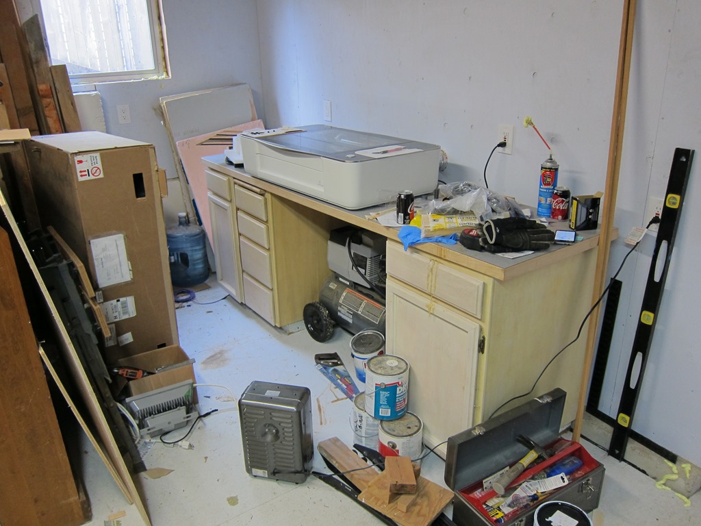
My glowforge lives in a workshop I have that I’ve been working on fixing up. The workshop was bare studs but now it has plywood walls and some improved electrical.

IMG_9196

As you can see, it’s sitting on top of some old and tired cabinets that I don’t use for storage because they don’t work very well, and a counter that sags in the middle. I need something to be better at holding both the glowforge and the other stuff I want to do down here (in particular, I need a place I can put a reflow oven for some electronics projects).

My initial thought was to price out some replacement cabinets and a countertop, but that quickly started looking like $800 – $1000 for the cheap stuff. So, what other alternatives could I use?

I was inspired by Mike’s table in this forum post:

That’s just a cheap home depot storage rack, only using part of it. I found a rack that was like it at Home Depot, and it was only $60:

But… It was only four feet wide, and I wanted some space to put my laptop and other stuff next to the glowforge. So, I started looking for racks that were wider but still 24” deep. The ones I found were a lot pricier; something like $150 or so.

Time passed, and I ended up on Costco’s website, and decided to search there.

1

What have we here? 60” wide, 24” deep, and a full 72” tall. $170, so not super cheap, but pretty close to what I wanted. I could put four shelves at the bottom for flat goods, and then one shelf at the top, and the glowforge would be at waist height. And wheels if I wanted them.

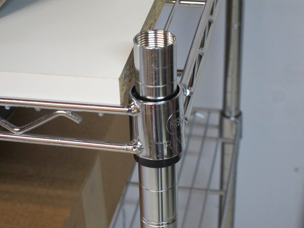
It took about a week to ship, and the box it showed up in was heavy. 104 pounds heavy. I dragged it off the front porch and into the garage, opened it up, and found that it was just what I expected. 5 shelves, and – to save on shipping costs – the corner posts come as two sections that screw together. I did some measurements, and realized that if I didn’t use the casters (it comes with both casters and normal feet), the length of he bottom posts was almost exactly counter height, which meant I could do a build that was pretty much at counter height.

And… if I only used 3 shelves on that, I could use the remaining parts – the upper posts and other two shelves – and build a second countertop-height system to go next to the first:

IMG_9197

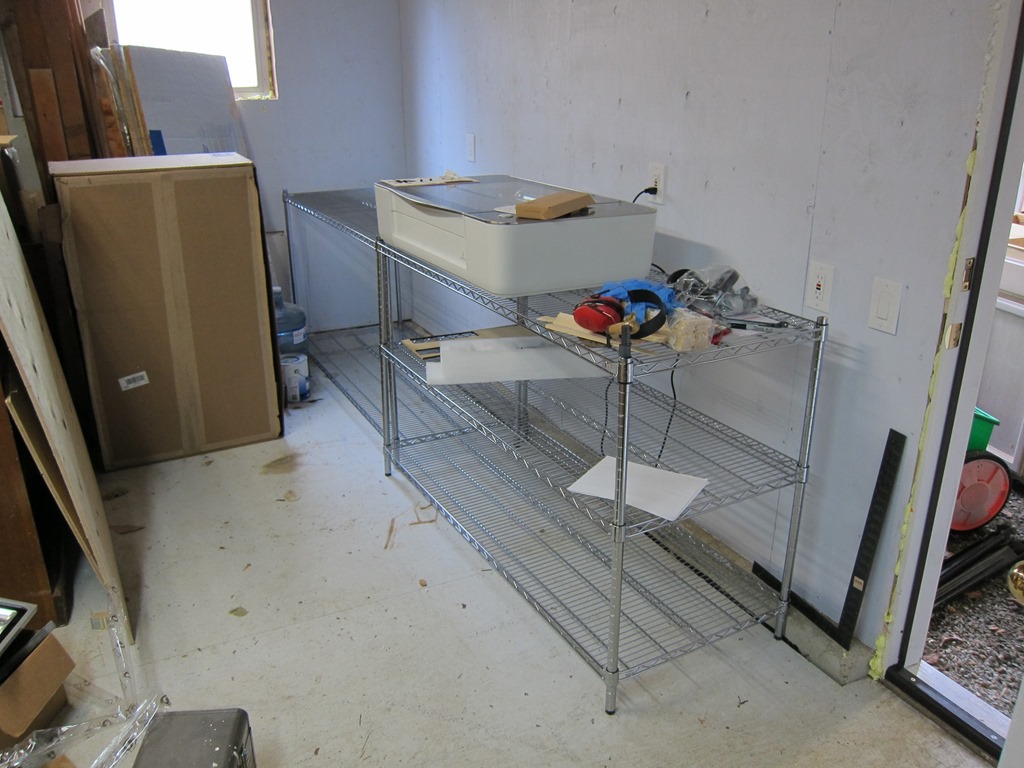
So, that $170 got me two counters – one to hold the glowforge, and one to hold whatever else I want to put next to it. But if you didn’t want the second counter unit, you could easily put the other two shelves on the glowforge part and get a lot of storage for flat materials. And have it on wheels if that is useful for you.

There was only one problem. Wire shelves aren’t the nicest things to put stuff on as small items fall through the openings, and you can’t write on them either. What I needed was a countertop to go on top. There are a few options:

  • Buy one of the ikea countertops – like this or this – and trim them down. I would need two in this case, and that would be another $120. Decent idea, and I like the black look. So yes for fancy, but no for this setting.
  • Buy a full sheet of melamine. My lumberyard will sell me a 48” x 96” sheet for $35, and that would do both counters with some left over. Downside is that the 1/2” sheets are about 65 pounds and a bit of a pain to transport. And the exposed edges aren’t white.
  • Buy some pre-drilled shelf panels. These are meant to be used for the sides of cabinets with shelves in them. $38 each, and I would need two of them.

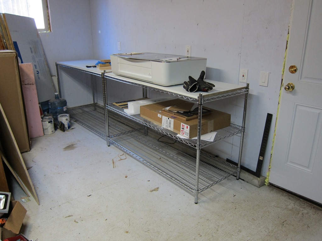
I was going to go with the big sheet for $35, but then I got to looking around and remembered that we had some extra Ikea shelves hanging around. They are about 29” x 24“, so I’ll just need to trim a bit off of them to make them the right depth (if they are trimmed to 23.5” they will fit between the front and back wire sections and not slide around). When I went and did that, I found that two of the shelves are almost perfect in length between the posts, and everything looks quite tidy. Here it is.

IMG_9199

Plenty of space for a laptop on the right side, lots of storage for stock underneath. I might build some vertical storage on the left side; not sure yet.

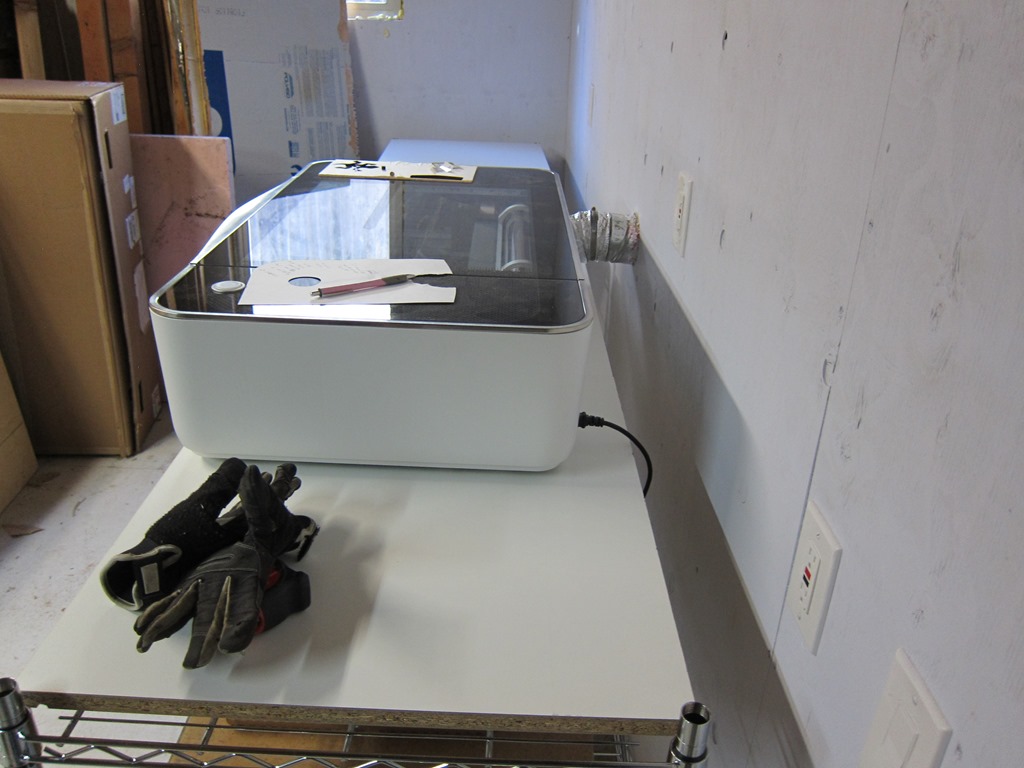
IMG_9200

The shelf is plenty deep; I have mine towards the front to make the exhaust fit better. What I really need to do is trim a couple inches off the duct.

If you are going two countertop-high units, you’ll want to drop the first one down one inch so that everything is level. It looks like this.

IMG_9201