Browsing posts in: Pinball

WPC opto issues…

I’ve had an ongoing issue with my World Cup Soccer ‘94 – at certain times in the game, it will push balls into the plunger lane when it shouldn’t. That points to some sort of problem with the sensing of the balls in the trough at the bottom of the game.

WCS is a WPC – I think that means “William Pinball Controller – and one of the nice features of the software that runs the game is that it has some test software that lets you visualize the state of the switches in the machine:

In my testing, the trough switches work fine when there is a ball in them, but if there is no ball in them, they cycle between open and closed. That is likely to be the problem. I verified that the trough LEDs and opto are functioning correctly and I’ve done the usual “unplug and replug all the cables” approach, so it’s time to dig further.

I did a post on pinside – which yielded no responses – and then pulled out the 7-channel opto board. It looked fine, but when I put a VOM on it, I found 10 VDC and 2.7 VAC. Not good.

I should mention that this machine had some issues on the power driver board, so I took an opportunity to recap it, so I knew that my supply voltage was fine. which meant the most obvious culprit was the 100 uF cap on the opto board.

Except it wasn’t; replacing that caused no real improvement. Which led me back to the power driver board where I found similar voltages at the test point. I pulled the board, found no continuity between the – terminal on C30 and ground, which meant I damaged the through-hold plating with my recap and it just took a while to fail. I added a jumper between the cap terminal and the adjacent ground trace – it would have been trivial to add a trace there, but for some reason they didn’t.

Put the board back in the game, everything works fine. Later I found a note in the WCS repair guide that said, “if the optos are malfunctioning, it’s usually a connection on C30”. Yep.


Fixing Bally/Williams Opto troughs

I had a problem with my WCS serving multiple balls, and I thought I’d share the approach I used to fix it.

I had looked at the switch tests, but the problem was somewhat intermittent so that didn’t really help.

I pulled the whole trough unit out; that took:

  • Two screws from the bottom
  • Removing the bottom playfield cover below the flippers
  • Removing 5 (?) screws from the top

That loosens the trough. I then took out the 4 screws that hold the solenoid to the trough, unplugged the connectors, and it was out.

Test the LEDs

I started by testing the LEDs. Through trial and error, I found that a 1K ohm resistor and a 5V supply resulted in a current of about 4mA, and since that’s within the spec for most LEDs, I stuck with that. Hook one end of the supply to the common and the other to the individual LED pins, and verify that they all light up.

They’re infrared LEDs, so you can’t see them, but pretty much any digital sensor can; a camera, your phone, etc. It’s simpler to remove the board from the trough before you do this.

All the LEDs on my board checked out.

Test the phototransistors

Keep your setup to turn on the LEDs as we’ll need it for this step.

Using a ohmmeter, connect one end to the common and then connect the other end to the pin for the LED that you currently have on. You should see about 4K ohm when the LED is on and something around 1M ohm when your hand is blocking the light. If you don’t see any difference, swap the leads from the ohmmeter around. You may have to turn the lights out to get 1M on some of the phototransistors as you can get room light reflecting into them.

Work your way down through each LED and phototransistor and verify that you are getting the right settings. If you find one that isn’t reading correctly, or consistently, it is *most likely* a connection issue.

I would start by verifying the connections; with one lead connected to the common pin, verify that you have continuity to all of the phototransistors; one of the pins on every one should be zero ohms (or close to it) and connected to the common.

Then repeat that from each of the LED pins on the connector to the non-common phototransistor pin. You should see zero ohms on each of those as well.

My issue turned out to be a rework issue; the #6 phototransistor was replaced by somebody and they either messed up the through-hole or didn’t resolder it correctly, so it was only making contact on the LED side of the board sporadically. Rather than pull the board off and try to resolder the phototransistor, I added a small jumper wire from the pin to the phototransistor.

Everything tested fine, and no more double balls.


WPC Driver board Upgrade

I finished the upgrade of my WPC driver board today. It was fairly simple despite Williams using a crappy circuit design; instead of using vias to carry power from one side of the board to the other, they rely on component leads to do that, presumably to save cost.

If you do this yourself, after you remove the component make sure to tin the ring on the component side with solder and overdo the amount of solder you use if you can’t see the component side; I had to redo several of the big capacitors because they had great solder joints on the bottom but not enough solder to grab onto the other side. So, on those components, jam more solder in there than you would normally do, and I also recommend grabbing the schematics, an ohmmeter, and checking for continuity through the hole.

WCS Power Driver Board Voltages

I measured the board voltage for future reference, both with only the input power connected to the board and the game in attract mode, using a quality Fluke voltmeter.

AC is measured to look for poor filtering by the large capacitors on the board; as the capacitors degrade there will be more AC present on the voltages.

Test point Input DC Input AC Attract DC Attract AC Description
TP1 15.83 0.002 13.8 0.1 +12V filtered but not regulated
TP2 5.02 0 5.01 0 +5V regulated Digital supply
TP3 12.03 0 11.7 0 +12V regulated digital supply
TP4 0.393 0.6 3.80 0.06 zero cross
TP5 Board ground
TP6 77 0 76.2 0 +50V for solenoids, flippers
TP7 22.26 0.003 21.8 0.01 +20v flash lamps
TP8 18.52 0 13.9 – 15.1 0 – 2 +18 to lamp columns


WPC driver board issues

My WCS 1994 is having some issues; the DMD display is showing static and now the game is behaving strangely.

I’ve been using the guide here, but I’d like to share some other data I’ve gathered since I didn’t find it elsewhere.


Test point Working DC Working AC Problem DC Problem AC Description
TP1 14.7 0.63 13.5 0.08 +12V filtered but not regulated
TP2 4.93 0.01 4.97 0.001 +5V regulated Digital supply
TP3 11.92 0.008 0.758 0.122 +12V regulated digital supply
TP4 0.37 0.63 3.62 0.06 +50V filtered
TP5 0.03 Board ground
TP6 73.2 0.2 – 0.8 75.1 0.01 +50V for solenoids, flippers
TP7 21.7 0.09 21.6 0.04 +20v flash lamps
TP8 15-17 0.2 (ish) 11-14 0.8 (ish) +18 to lamp columns

“Working” values come from my Twilight Zone (working), while “Problem” ones come from my WCS (not working).

What can we tell from this?

Well, a few things. The obvious issue is TP3; it is less than 1 volt when it should be around 12 volts, and it’s letting a lot of AC through at all.

Time to pull out the schematics.

image

Sorry, that was the best image I could pull from a PDF; the paper version isn’t much better.

Basically, we have power coming in from the left side, which should be a nice healthy 18volts (measured at TP8). It goes through two series diodes that will drop the input by a little over a volt, and then it goes to an absolutely-standard 78xx linear regulator circuit; a capacitor on the input, a 7812 (for 12volts) and a capacitor at the output. 78xx regulators are pretty robust, so let’s see if we’re using it correctly…

Like most linear regulators, the 78xx series has some limitations around input voltage; it requires about 2 volts of headroom to be able to give us the output voltage, so we should be looking for 14 volts coming in. We have 11-14 volts – it fluctuates because the lights are flashing in attract mode. That 11-14 volts isn’t enough to consistently give us enough voltage for the 7812 to give us a nice 12 volts.

So, we don’t have enough power coming in, so that is the problem, right? Well, not so fast. Based on what I know about the 78xx regulators, one would expect that if the voltage drops enough so that you don’t have a full 2 volts, you will see the output voltage slowly drop down.

I pulled out a 7809 and hooked it up to my variable power supply, and found that this was mostly true; the dropout voltage was about 1.2 volts (two diode drops). That means I would expect that the 7812 would put out less voltage but something close to 12V.

So, that suggests that we have two issues going on; we don’t have enough voltage coming in for the regulator to work and the regulator looks fried. That is supported by some data I had before this where the game was acting very weird and the voltage at TP3 was fluctuating all over the place. So, a new 7812, and it would be a good idea to replace the 1n4004 diodes and the electrolytic capacitors in this section at the same time, since this board is nearly 25 years old.

Looking at the input voltages at T8, note that there is a decent AC component in the DC voltage – about 0.8 volts. Back to the schematics:

image

This is also really simple; we have AC from the transformer coming in, going through a full-wave rectifier, and then there are two honking big 15,000 uF electrolytic capacitors. As these capacitors age, they are going to lose some capacity and have an increased internal resistance; both of those make them worse at filtering, so it’s time to replace those as well. It’s possible that the AC that they are putting out ended up hastening the end of the 7812.

It’s typical to replace both the capacitors and the bridges when the board is reworked, just to make sure, so I will probably do that.

I am a little concerned by some of the values I see on my TZ board; there are some indications that the caps there need replacement as well. I’ll do the WCS and then compare it to the TZ one.


A pretty good twilight zone topper

Twilight Zone, being one of the top pinball machines with collectors and having a very good theme, has led to it being heavily customized, some of them being functional, but most just being ornamental, to make the machine more fun.

One of the cooler ones was done by a guy who took a small hallmark ornament that looked like a TV, put a small LCD display in it, and then used it to display pictures from the TV series while you played. It’s tiny (maybe 1.5”), and it fits inside of the game. And then somebody else did one that showed video.

I was thinking that it would be cool to do something that was game controlled, which is the whole reason I built the WPC pinball lamp decoder. And, instead of making it a small one that would go on the playfield, I decided to make it slightly larger and make it as a topper.

A topper is simply something ornamental that goes on top of your pinball machine. They are almost always lighted in some way, and, with a few exceptions, not controlled by the machine.

Mine would be. Twilight Zone has a bunch of different modes, and my plan is to detect those modes (and other events) by decoding the light state, and use that to play *appropriate* clips on the topper.

I needed a good enclosure. And, thanks to Ebay, it was simple to procure:

This is an early Sony 5” TV, and it was a bit of a design coup for Sony; nobody was doing TVs this small at the time. I toyed with the idea of just using it as a display, but then I took a look inside:

That is one of 3 circuit boards. These TVs have a reputation for being very hard to work on, and I don’t what that sort of project, so we are going to use it as an attractive case instead…

I plan on using as many of the controls as possible; at least the on/off switch and the volume knob.

For a display, I need a small LCD. I found one that is designed for a rear-view camera. Here’s a test-fitting in the case:

Fits but barely on width, but the height is less than I would like (the display isn’t really 4:3). Hmm. If I put it behind the original CRT protector…

That will likely work better. Assuming I stay with this display (and I think it’s the biggest one that will fit without hacking out the control section on the right), I will laser-cut an oval trim plate out of black acrylic that will cover the gaps. I’ll also modify the lens to get the display more forward.

and one more photo of the display working…


A bit about pinball

You may or may not know that I’m a pinball afficianado. Yes, yes, “ever since I was a young boy, I played the silver ball…”

During the arcade boom of the early 1980s, arcades were everywhere, and while they generally focused on video games, there were always a few pins. I spent lots of time and money on both, but pinball had more of a fascination, for three very important reasons:

  1. If you are decent on one pinball machine, you are decent on all of them. This is very much not the case on arcade machines; your skills on Defender help you when you play Tron, but you aren’t automatically decent.
  2. The physicality is much better. You get to shake the machine. No, you are *required* to subtly nudge and shake the machine while you play if you are going to be a good player. You work on your advanced moves. And you enter a society of players who know how to play the right way. It’s a bit of a craft.
  3. You can win free games. Plus, the difficulty level on a pin is mostly linear; yes, it becomes a *little* harder on most games as your points go up, but it’s not a lot harder. What that means is that once you are good, it becomes easier to get high scores. And, every once in a while, probability and skill will align, you will walk into an arcade, put one quarter into the pin, and play for half an hour, with the game knocking to announce your skill when you win a free game. And then, after that time, you will turn to the 12-year-old kid who has been watching you play and say, “I have to leave. Do you want my games?”

So, anyway, I played a bunch of pinball in my young days, but it tapered off when I got older because pins and vids became much harder to find. You could find them in bars, but I don’t do well with cigarette smoke, so I didn’t play as much as I used to.

Then, sometime in my 30s, I realized that a) it was possible to own a pinball machine, and b) I could afford to do so. So, I craftily bought a Williams Bad Cats:

The reason it was crafty is that I bought it because a) it was a relatively inexpensive machine (I think I paid $800 + shipping), and b) it was my wife’s favorite machine.

I reconditioned it, played it for a while, but there was still a problem.

I wanted a Twilight Zone…

Twilight zone is complex machine. A really complex machine, with ramps, ramp diverters, a working pinball machine, a magnetic mini-playfield, and a impressively complex ruleset. Oh, and it has a lightweight ceramic “powerball” that moves really fast, two different 3-ball multiballs, and – if you are worthy – “Lost in the Zone”, a 6-ball timed multiball mode.

In fact, it was so complex that it didn’t really do well commercially; novice players found it too challenging and confusing.

But skilled players loved it, and made it a hot commodity in the resale market. I was lucky/smart enough to buy mine around 10 years ago, when machines are a bit more plentiful, and paid around $3500 + shipping to get it. These days you will probably play twice that.


Pinball Lamp Matrix Decoding–Completed board

I got the boards back from OSHPark a while back, and got around to populating them. Though I have access to a real reflow oven, I’ve done boards like this with the heat gun method in the past, so I got out the solder paste, put it on the solder pads, put on the shift registers, and then went out to the garage.

I use an old license plate as a board holder, so the board goes on that.

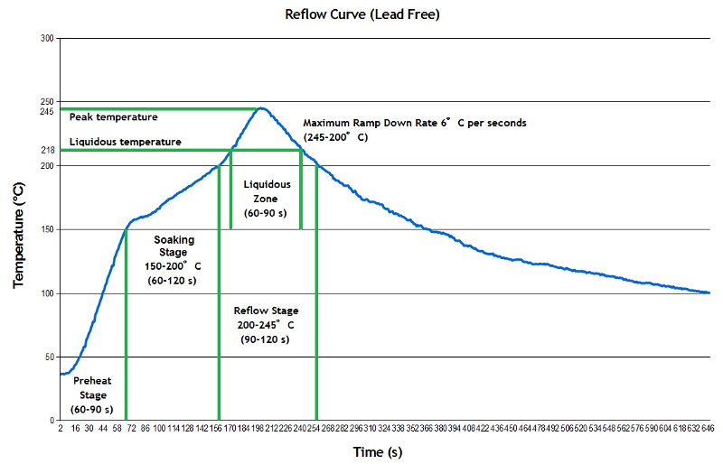
Real reflow ovens use a time/temperature calibrated curve.

Basically, there’s a long soaking stage to gradually bring all the parts up to temp, a ramp up until the solder melts, and then a cooling-down period. I attempt to duplicate this with the heat gun, though it’s really not very precise.

The hard part with the heat gun is keeping it at a distance where it does not blow the parts around on the board; as the board heats up the flux will start to flow and the chips want to move. A little repositioning with a toothpick fixes that. You keep heating until you see the solder reflow, make sure it’s reflowed around all the parts, and then remove the heat.

And you get this:

The 34-pin connector and the two test point connections were hand soldered. I do need to test the board itself and then hook it up to the pin and see if it works.