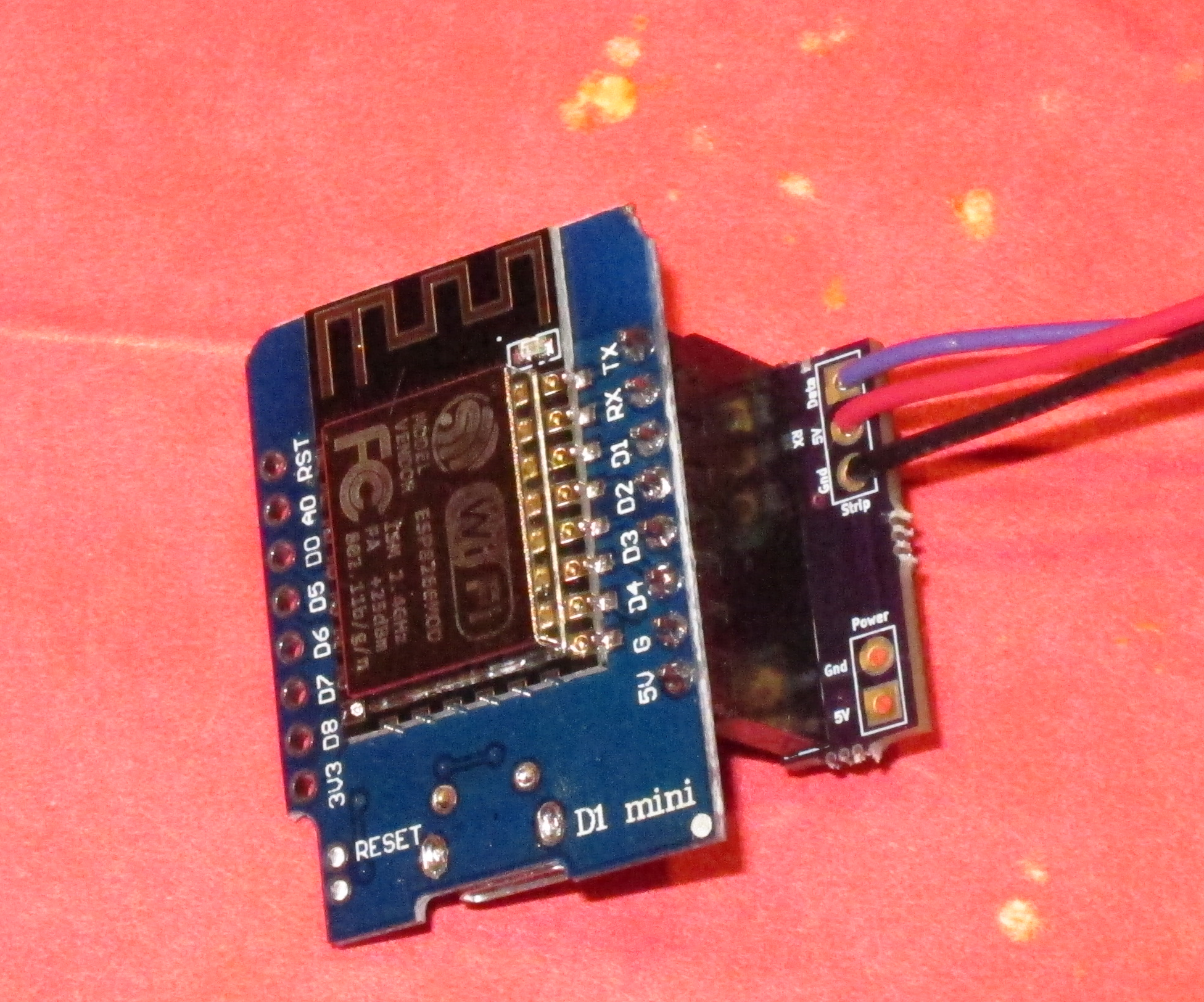
To connect the Eagle controller is simple; there are only three connections to make:
The following connections need to be made:
- The black wire from the strip (or globe) should be connected to the ground pin
- The red wire should be connected to the 5V (5 volt) pin
- The data wire (purple from the globe) should be connected to the RX pin.
This will be enough for the controller to work if powered through the USB mini jack. This is fine for testing, but has several drawbacks:
- Each WS2812 LED will draw 60 mA of current if it is full bright. There are 33 on the globe, which means that full white will draw 60 * 33 = 1980 mA = 2 amps. The USB connector will not be able to supply that amount of power, so you will not get full brightness.
- The Eagle controller has a diode so that external power will not power the USB jack. This means that instead of getting 5V to the strip, you get about 4.4 volts to the strip. It also means that there is a lot of power being dissipated by that diode, and it will get *hot*; hot enough that it or other components on the board may fail.
To avoid these issues and enable full brightness, you need an external 5V power supply that can supply sufficient current. It can be connected to the 5 volt and ground connections.
Using the connection board
Newer versions of the controller ship with a small adapter board to make these connections easier.
We will start by soldering a male header to the series of pins on the right side of the controller with the pins sticking out underneath. You can get by with just using pins for 5V, ground, and RX, but there’s no harm in soldering all 8 pins. Here’s how I do it:
Place the header pins into a solderless breadboard with the appropriate spacing. We put pins in on both sides so the board will sit level, but we are only going to be soldering the ones at the top.
This step may have been done for testing purposes.
It should look like this when the pins are soldered:
Now, we need to solder a female header to the adapter board:
The header should stick out above the board in this orientation. To do the soldering, I balance the board on the female header and use the other strip of female header to hold the board level:
Solder all 8 pins across the top.
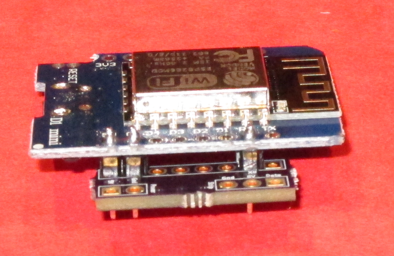
This is the controller with the male header and the adapter board with the female header. The male header simply plugs into the female header.
The wires to the LEDs are then connected to the upper 3 terminals on the adapter board, and the 5V power supply is connected to the lower two terminals.
Compact option
If the controller and the adapter are too thick, there is an option that is thinner:
In this option, the female header is omitted and the adapter board is soldered directly to the male header pins.
If you are really tight for space, you can solder the male header, remove the black plastic that separates the pins, and then slide the adapter board right next to the controller.


So, what do you think ?