How to become a better skier–Recommended exercises

This post collects the exercises that I generally recommend.

Sideslip

Find a moderate intermediate slope, and stop with your skis across it. Note that your ski edges up digging into the hill; that is what is stopping you from sliding sideways. Move your knees and ankles downhill until you start to slide sideways down the hill. It generally helps to stand evenly on both skis and keep your skis shoulder-width apart; if they get farther apart it’s much harder to do.

Once you have slide 10-20’, roll your knees and edges back into the hill to stop. Reverse and try it facing the other direction.

Repeat the stop part using a quicker roll and ending up with more of an edge.

What we are working towards is an angulated position.

In the inclined position, the center of mass of the body is a long way towards the inside of the turn. To get to the next turn, that body mass needs to be moved up,  over the skis, and to the inside of the next turn. That takes quite a bit of time, and that’s generally the reason for a long transition between turns.

In angulation, the body is bent sideways at the waist, and most of the angle of the legs comes from that bend, with the upper body mostly upright. To go from one turn to the other just requires moving the legs to the other side, and that’s much faster.

Start by just leaning sideways against the wall, keeping your upper body straight. That is *inclination* or tilting. Now let your hips sag in but keep your legs straight. That is hip angulation. Finally, let your knees bend a bit and the curve will increase. That is hip and knee angulation.

There are two points of being angulated.

First, allows us to create significant edge angles. Second, it allows us to switch edge angles from one side to the other quickly because all we need to do is switch the legs; the upper body stays mostly where it is.

That angulated position is what we want to have when we stop in a sideslip. It’s also what we will want in a turn.


Fan Progression Carving Introduction

This exercise works towards getting the ski in a solid carving position and just letting the ski do all the work. Do the sideslip/angulation exercises so you understand the body position we are going for first.

On a medium intermediate slope, point your skis down the hill just enough that you start moving forward at a slow speed. As you gain speed, roll your knees and ankles into the hill; that will cause the skis to smoothly arc in a large turn until they turn up the hill and stop. Do not twist the skis to turn them; let the skis do all the work. If you are doing it right, you should see two distinct parallel tracks in the snow. Repeat to the other side.

Now for the progression part; repeat the exercise but start by pointing your skis closer to the fall line so you end up going a bit faster before you start the turn. When a given starting angle feels comfortable, you can point your skis closer to the fall line.

The goal of this exercise is to pay attention to what your skis are doing and how your body position affects what they are doing; if you want, you can play around with shifting your weight backwards, which will generally make it much harder to complete.

You can push all the way to starting straight down the fall line, but note that this may result in some fairly high speeds and it may take a long time to turn and come to a stop.

WARNING: Your path on this exercise is not a typical skier path, so it may surprise/confuse people coming down the slope. Pick a slope that isn’t busy and make sure to look uphill before you start.

There’s a good video here that shows what it should look like. Make sure to watch it full screen.

BTW, this introduction is the gateway to large radius carved turns, which use the same technique, except they involve a turn both into and out of the fall line.

One ski skiing

This is a stance diagnostic exercise that I use all the time myself.

Pick a comfortable intermediate slope and start making intermediate turns. At the transition between one turn and the next, pick up the tail of the new inside ski 3-4” in the air and hold it up during the turn. This is great at troubleshooting stance; if you cannot do it, it means you do not have enough ankle tightness/forward pressure in the outside ski.

My advice is to do the following progression:

  1. Ski 10 turns doing this drill.
  2. Ski 10 turns thinking about getting the tails light but not actually lifting them.
  3. Ski 10 turns trying to get the same feeling in your outside ski but ignoring what the inside ski is doing
  4. Ski a whole run to cement that new outside ski feeling into your skiing.

This can also help your off-piste skiing; do the drill on a groomed run, and then try #2 on the ungroomed run or in bumps (you generally don’t want to lift the tail because the big increase in weight in the outside ski can cause it to sink significantly.

Shuffle turns

This is another stance diagnostic exercise; it’s also good to loosen things up if you think your stance is too static.

It’s pretty simple. Start your turn as you normally would, and during the turn shuffle your feet forward and back about 3-5” throughout the whole turn.

You will need a good forward stance to be able to do this, and you will need a smooth turning motion as well; you can’t do this if you are using a big rotary motion to pivot your skis across the path of travel.

Initially, just shuffle during the part of the turn where you can shuffle. In the advanced version, keep your feet shuffling the whole time you are skiing a series of linked turns.



Exercise, Weight Loss, and Low Carb Performance

This is the companion post for the presentation that I did of the same name.

I’ve written about these topics fairly extensively; if you want the longer version you can find it here. The video is intended to be more approachable and more practical than the ones I’ve done in the past and bring in some additional information about different muscle fiber types, their use in different kinds of sports, and how that might impact your fueling strategy.

References

The pretty graph that I complain about in the presentation comes from the following study:

Metabolic Factors Limiting Performance in Marathon Runners

The data for the graph came from this study:

Regulation of endogenous fat and carbohydrate metabolism in relation to exercise intensity and duration


The worst 50 watt speaker in the world…

I’ve been working on a project that I think is one of my stupider ones, and it’s time to share it so that I can move onto something that is slightly less stupid.

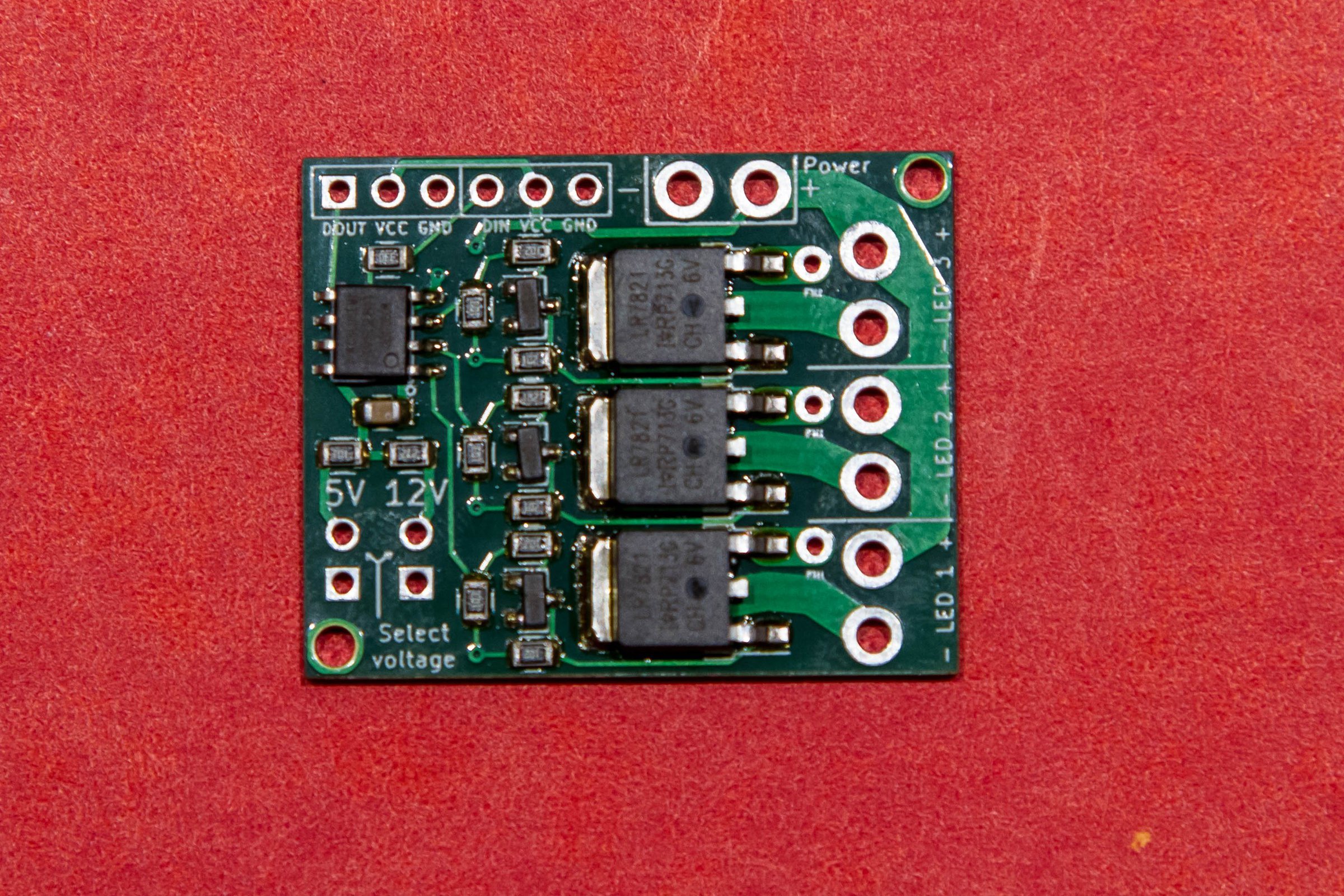
I build a little board that I sell on Tindie that allows you to use the WS2812 addressable LED protocol to drive bigger loads; so instead of having a tiny LED you could use spotlights in three colors.

WS2811 / WS2812 Extender

It has a WS2811 IC, some transistors to act as inverters, and then three hefty power MOSFETs to handle the load. It’s a pretty hefty circuit, but to be conservative I rate the the boards at 4 amps per channel with all three channels driven – which would be 50 watts per channel if running on 12V – or 8 amps with one channel driven.

I therefore need a test circuit to validate that these are working okay, and that’s simple an ESP8266 doing some dimming across the loads.

And for the loads, I have a series of four 12V 50 watt light bulbs – these would be used in RVs before LEDs became common. They’re nice and hefty and it’s easy to see if they are working. Here’s a video that shows the text fixture and the bulbs working:


MVI_0093 from Eric Gunnerson on Vimeo.

If you pay attention carefully – perhaps turn up your volume a bit – you will hear that the light bulbs are making a whining noise. That is because the WS2811 is running PWM at 2 Khz, smack-dab in the middle of the audible frequency range, and the light bulb filaments are vibrating at that frequency.

That was just a curiousity that I filed away, until I was testing a new set of boards and I had a thought:

What if I could change the frequency of the PWM?

And that little idea trigger a bunch of stupidity…

I dug into my supplies and found I had a bunch of unused ESP-32 boards leftover from when I ordered the 36-pin version instead of the 30-pin version.

image

I had sample code that did 16-channel PWM on the ESP-32 – the ESP-32 is almost ridiculously capable in some areas – and I ported that over to a new version, took one of my driver boards and pulled off the WS2811, wired them together, and got… nothing.

Played around some more, got more nothing. I just could not get it to work. The board would work fine when I drove it directly, but the ESP could not drive it. I also had trouble getting the LED on the board to work; it barely lit up at all. That should have been enough, but it took me an embarrassingly long time to figure out what I think is the problem…

Basically, these boards have a 3.3v regulator on it that is not up to the task. It claims to be an AMS1117, which should be a fine choice; that regulator has nice specs and can put out up to an amp of current; plenty for the ESP32. AFAICT, what it actually has is a cheap counterfeit that just barely puts out enough power for the chip to run but not to do anything useful. I could measure the outputs of the ESP and they looked fine as long as I didn’t put any load on them. I dredged a memory out of my brain that others had run into this issue, so now I’m left with a bunch of boards that don’t work, though I’m considering replacing the regulator to see if that helps.

I dug out one of my other ESP-32 boards, moved the code over, and it worked great on the first try. So don’t buy the other boards…

From concept to “music”

This section also took much longer than it should have, so I’m just going to mention the highlights…

The midicsv program is your friend if you want to convert songs into arrays of note values.

Midieditor was quite useful to simplify arrangements and fix up some of the midi notes, though the documentation is mostly absent.

Note quantization can be very useful if the midi file you download ends up with a new note starting quite a bit earlier than the note that it is replacing.

Excel is your friend when manipulating CSV files.

Midi tempo is complex. Basically, the note timing is expressed in terms of “ticks”. The header in the midi file specifies how many ticks there are per quarter note, sometimes expressed as “parts per quarter note” or PPQ. It will be something like 256 or 480.

Tempo is expressed in the number of microseconds per quarter note, and will be something like 500,000.

So, with a bit of math, you can determine:

tick time in seconds = (tempo / 1000000) * (1 / PPQ).

Then, based on the difference in ticks between when a note starts and when it ends, you can figure out the delay.

ESP-32 LEDC Fun

Conceptually, I wanted to have different PWM channels running at different frequencies. This turnout out to be far more problematic than I thought.

My first mistake was using the ESP-32 arduino HAL (hardware extraction layer) functions for the LED control subsystem. Conceptually, all I should need to do is:

  • Call ledcAttachPin() to attach a specific GPIO pin to a specific PWM channel (the ESP-32 support here is really nice).
  • Call ledcSetup() to specify the PWM frequency and resolution in bits that I wanted).
  • Call ledWrite() to set the PWM duty cycle (either 256 to turn the light off or 64 to turn it mostly on).
  • And that’s what I did. And it sorta-kinda worked in some cases, didn’t work in others. I finally called ledcReadFreq() and looked at the values I was getting back. Channels 0 and 1 were always the same frequency, but channel 2 was a different frequency. Hmm…

    After reading the non-arduino docs for the led control system, I came across the docs for ledc_set_freq(), which had a parameter named “timer_num”, and the description said “LEDC timer index (0-3), select from ledc_timer_t”.

    Ahh… There are only 4 timers that you can use, not 16. Unfortunately, the HAL abstraction gives the impression that you can set frequency individually on each control channel. You can, it just affects other channels as well. Digging into the source, I found this table:

    /*
    * LEDC Chan to Group/Channel/Timer Mapping
    ** ledc: 0 => Group: 0, Channel: 0, Timer: 0
    ** ledc: 1 => Group: 0, Channel: 1, Timer: 0
    ** ledc: 2 => Group: 0, Channel: 2, Timer: 1
    ** ledc: 3 => Group: 0, Channel: 3, Timer: 1
    ** ledc: 4 => Group: 0, Channel: 4, Timer: 2
    ** ledc: 5 => Group: 0, Channel: 5, Timer: 2
    ** ledc: 6 => Group: 0, Channel: 6, Timer: 3
    ** ledc: 7 => Group: 0, Channel: 7, Timer: 3
    ** ledc: 8 => Group: 1, Channel: 0, Timer: 0
    ** ledc: 9 => Group: 1, Channel: 1, Timer: 0
    ** ledc: 10 => Group: 1, Channel: 2, Timer: 1
    ** ledc: 11 => Group: 1, Channel: 3, Timer: 1
    ** ledc: 12 => Group: 1, Channel: 4, Timer: 2
    ** ledc: 13 => Group: 1, Channel: 5, Timer: 2
    ** ledc: 14 => Group: 1, Channel: 6, Timer: 3
    ** ledc: 15 => Group: 1, Channel: 7, Timer: 3
    */

    Ah. I’m not sure why the mapping works the way it does, but that’s the way it does, and channels 0 and 1 always use the same timer. And I think that’s a decent reason not the use the HAL, but since my code was written and I was lazy, I just mapped my channels 0, 1, 2 to 0, 2, and 4, and things were fine.

    Which finally led to me declaring success, and I can therefore offer up the following videos.

    Project video

    Here’s a project video that shows the result. The light bulbs are terribly inefficient; with 40-50 watts of input they produce a very tiny amount of sound.


    Summary

    So that’s the stupid project. The software supports 3 channels but I burned out the third channel on my board when I was having issues with the crappy ESP, and since two channels is barely discernable, there’s no reason to go farther. If you would like to see the stupid code, it is here.


    Sven Hills of Kirkland 2020

    As I have noted a time or two, 7 hills is probably my favorite ride; it meets my requirements in terms of hilliness, it has great staff, and – being local – I don’t have to travel or get up at an ungodly hour to do it.

    I first rode it in 2005, and have ridden it mostly every year since, except when it’s been rainy. I typically do the “metric century” version, air-quoted because it’s only 59 or so miles rather than 62.1371 miles as one might rightly expect.

    For good reasons – the 2020 edition was cancelled.

    But checking around, I found an alternative…

    Planning

    This is not a ride that requires a lot of planning, at least if I have normal amounts of training in my legs. I’m a little on the light side for miles and up this year, but close enough. I rode up Seminary a week ago and felt pretty good.

    On the day of the ride I woke up at about 5:30 to the birds in the greenbelt behind our house, looked outside, and found the pervasive mist that Seattle is so good at. That’s okay; my expected departure time is fluid.

    I’m not sure what distance I’m going to ride today; there’s the classic 40ish miler, the metric century, and the full century. All of the routes are additive; on the short version there’s a point where you can turn off to do the longer versions, and on the metric century, a point where you turn off to do the whole century. That is both an advantage and a curse depending on the state of your goals from minute to minute.

    I find that I need to correct a statement I just made; I know that I’m not going to ride the century. Two years in a row I signed up for century and then found an *extremely* good reason to stay on the metric century route when I came to the turnoff, and I then realized that the century isn’t for me. I’ve ridden the additional 40 miles and I’m apparently just not very excited about it.

    Perhaps the biggest decision I need to make is what to wear. A quick glance at the thermostat shows there are only 52 F’s outside, and that’s too few F’s to just go with a jersey and shorts, so it means arm warmers – which I can take off later when there are more F’s – and a light vest – also jerseyable. It’s a little cold to skip the leg warmers but I think I’m going to anyway; my knees may get cranky but the hills will help keep them warm; leg warmers are a pain to take off and my team car is never handy to hand them off.

    I stuff some food into my pockets, though I don’t really need to eat that much on rides unless I’m going to push the pace and I don’t plan to, though that will change depending on how my legs feel. Cheez-its, a bit of trail mix, and a somewhat ride-worn honey stinger waffle go into one pocket.

    Start

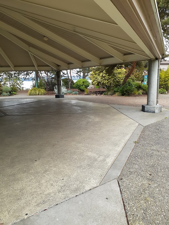
    I show up at the start pavilion on the Kirkland waterfront and pick up my packet. There seems to be little organization but that’s okay; I get my number and put it on my jersey:

    image

    I know the route pretty well – well, very well – but I take a look at the route guide:

    sven hills

    Seems about right…

    I head towards the first hill, Market street. Market was quickly dispatched, but on the downhill there was a detour back uphill and I opted to cross the street and ride the sidewalk for a bit until I could get back on the road down into Juanita. Up Juanita, down Holmes point on a really pretty section of the ride, and then to the base of Lord Uppity Upperton, sometimes known as “Seminary Hill”. Legs felt okay and I rode up the hill 2 gears up; I’m trying to ride my granny 34/32 less to build up my legs a bit more, so something like a 34/27.

    At the top, I turned left and stopped to take off my vest, and on the descent I hit road construction #4 and #5 of the day. I ran into another guy who I didn’t talk to because reasons, he caught up with me waiting for the annoying light (you know the one), and we started up Norway together. I decided to stretch my legs a bit and targeted 225-250 watts on the climb, finishing at the top by myself after road construction #6.

    The descent was still a little moist so I took it slower than usual, and then took my super-secret back way to get to 132nd and then over to the food stop at the Evergreen Health parking lot. It’s always nice to get off the bike for a few minutes and I had part of a honey stinger and some water; I decided to skip the lines for the food and headed back out.

    image

    From here the route winds northward until the descent on Brickyard, where I was obstructed by a bus on the descent which turned out to be a good idea as it was still a tiny bit damp. Talked briefly with another cyclist on the next section as I headed towards Hilly McHillFace (aka “Winery”). This is the steepest hill on the route but the pitches are pretty short; I ran it +2 on my gears and stood up a lot. One of the highlights of the ride is the special feature at the top of winery, but in this case it was more of a do-it-yourself version.


    Sven Hills top of Winery Climb from Eric Gunnerson on Vimeo.

    At the top, it’s a quick run south to the second food stop – which I skipped – then down into the valley onto willows and heading south. At no point did I consider turning left on 116th to do the metric version; my legs were a bit tired and I’ve been having some seat issues that make long rides less than comfortable (always know your excuses up front), but honestly I really just didn’t think about it.

    So, up the last hill – on which I passed a total of zero cyclists – a couple of nice descents, and then on to the finish line for the… ceremony?

     20200526_104322

    I did pick up some swag; it wasn’t what I expected but I have made some progress:

    IMG_9725

    All-in-all, not a bad substitute considering…


    First assembled PCB…

    I’ve ordered quite a few PCB boards, but this is the first time I’ve paid for assembly as well. Documented here so that I remember the steps. Instructions here.

    1. Do the PCB design. Duh.
    2. Find components in the JLCPCB component catalog. Extended ones require a flat $3 fee.
    3. Annotate the schematic components by adding a column named LCSC and putting the LCSC number in that column.
    4. Create the BOM from Tools->Generate BOM. This will fail if you have any spaces in your filenames as the xslt processor they use has issues, but it will create a .XML file in your design directory.
    5. Go to d:\data\electronics\bom where you will find msxsl.exe. It will work correctly. Modify a batch file to use that file and generate the output CSV file.
    6. Edit the output file. You will need to edit it to remove parts and columns you don’t need. I imported it into excel and then saved as a .xsls file.
    7. In the PCB editor, choose File->Fabrication outputs->Footprint position. Format = csv, units = mm, files = one file per side, footprint selection = with INSERT attribute set. This will generate a front and back file.
    8. Edit the output file so it has the following headers: “Designator,Val,Package,Mid X,Mid Y,Rotation,Layer”
    9. Generate gerbers as usual.
    10. Go into the jpcpcb quote too. Upload the gerbers.
    11. Choose “assembly”
    12. Upload the BOM and placement files, and look at the rendering. Carefully validate the rotation of active components; there are apparently two standards. If you need to modify the placement, go edit the output from step 7 and edit the rotation column.

    An ESP-32 Remote Control–Update and Version 1.0 case

    About 3 months ago, I wrote a post about an ESP-32 based remote control I’m building. Conceptually, what it does it allow you to press a button and hit a specific web endpoint.

    Since the introduction, I wrote some code and got a prototype kindof working – the touch inputs on the ESP32 work fine, the deep sleep works okay, but I ran into a few problems.

    First, the ESP32 can run on 3.0 volts but only kindof, and if you use two AAs their voltage drops pretty quickly to the point where the ESP stops working. Which means I needed a better power source, which means lithium based. I looked at primary (non-rechargeable) lithiums but they are also 3 volts (IIRC), I looked at lithium-ion, but 4.7 v is a really inconvenient voltage for ESPs; you need a regulator to get down there. Plus the 10850 cells are a bit big. Then I settled on LiFePo4 batteries, which very conveniently have a nominal voltage of 3.3 volts and are the same diameter (but shorter) than a AA, so they work well for packaging.

    I bought a little battery monitoring board to protect the battery, but I’ve decided to skip it for this version. So, I think I’m set for batteries.

    The second issues came up during my deep sleep testing. The ESP32 can get down to 10 uA in deep sleep, which looks great, *and* it supports “wait on touch” where it will turn on based on a touch input, which is also great. But…

    The devkit boards that I have don’t support using it that way; even with the power led removed I think I was seeing about over 10mA when the ESP was in deep sleep. Not good enough. Some people have hacked their boards to remove some of the components, but traces are tiny and the board is dense, and I gave up after a few tries. I could use a module programmer like this which pulls the dev kit components onto the programmer and leaves just the raw board, but the problem there is I need a mounting solution that lets me program the same module every time.

    What I really need is the dip part of the devkit board without any of the power supply or usb stuff and an adapter to hook that to the module programmer.

    Since I haven’t figured that out, I went with the best deep sleep approach that I know, a rocker switch. I’m thinking that will get the power use all the way down to 0 uA.

    The case

    I have some plans for the version 2.0 case, but those require a fair amount of prework and new tools, and it’s nice enough that I could really use the remote *now*, so I went with with the easy approach – a laser cut box.

    For touch points, I wanted some screw together pieces or screw studs, which I finally discovered were commonly known as “chicago screws”.

    Chicago Screws - "Flat Beveled" Design - Solid Brass (10-pack ...

    I wanted them in brass so that I can solder to them. The ones I got are 1/4” (6mm, actually) in length, which would be fine for my “real remote” design, but meant that I need to use 1/4” plywood for the face.

    I did the design in Fusion 360. This design was not one of my better moments. I did the face in 1/4” but the sides on 1/8” so they would be thinner, but it turned out that I don’t have any 1/8” plywood left; what I have is 1/10”, so I had to redo the design. Then I measured the size of the studs very accurately with my calipers and then entered the shaft length (0.235”) instead of the shaft diameter (0.165”). And the power switch was too close to the corner so the top and side wouldn’t fit. Then I cut the top piece out of a piece of 1/8” scrap, so it was too big.

    More trips back and forth than I had hoped, but it’s only computer and laser time plus a bit of wood, so it wasn’t that bad. Here’s the result:

    IMG_9719

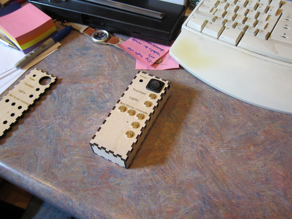
    Which is honestly pretty nice. The labels are engraved into the wood, and all it is missing is the power LED. The current plan is to glue the sides to the front and leave the back removable for access, but it’s not clear to me how that is going to work yet.

    Video here:


    Next up will be wiring up the front panel, assembling most of the box, and then hooking in the ESP and battery.


    French Cleat Electronics Workbench…

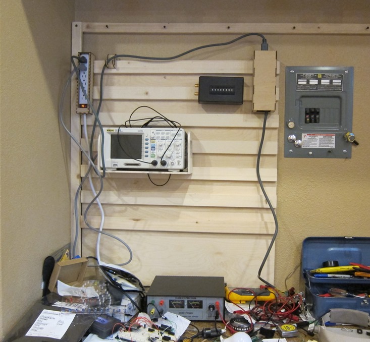
    IMG_9709

    I’m not known for the cleanliness of my workspaces; my office desk is a mess right now, my garage workbench is a mess, as are my other workbenches.

    But my electronics one is messy enough to be problematic, and the root problem is that there’s just too much stuff one the workbench; power supply, oscilloscope, toolbox, solder station, hot air rework station all take up a lot of space, and the work surface doesn’t have lot of depth, so I end up with a small clear workspace even without clutter.

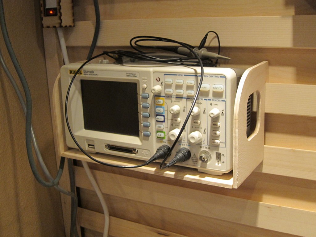
    A while back I was looking at my Rigol scope, and thought that I might have more room if I could mount it on the wall. And that obliquely led me to the current project.

    FH18MAY_586_00_006-french-cleat-tool-wall-featured

    I’ve been watching some woodworking on YouTube, and that led me to a series on french cleat walls. They are pretty popular for woodworking shops as they keep all of their tools handy. Looking at my garage space – where I do some woodworking-adjacent projects – I don’t have a lot of wall room for one of these, and most of projects I do occur elsewhere, so I wanted to keep my tools in their boxes. Not a great solution there.

    But that triggered a thought about my electronics space; I don’t move my tools around and I could use the organization.

    So I went looking in my garage and found that I had some leftover 12mm baltic birch plywood from another project, and I acquired some 2×3 pine for the cleats.

    Making the cleat wall is pretty simple; you just cut your cleats wood at a 45 degree angle and then attach it to the plywood using a regular spacing. If you want details, here’s a video I did of the process:


    I took the wall down to my workbench and attached it to the wall. Then it was time to start figuring out how to attach items to the wall; this is generally some sort of shelf or box with the mounting tabs that hook onto the cleat. First up was the oscilloscope, partly because it was big and partly because it was straightforward to design.

    Oscilloscope Shelf

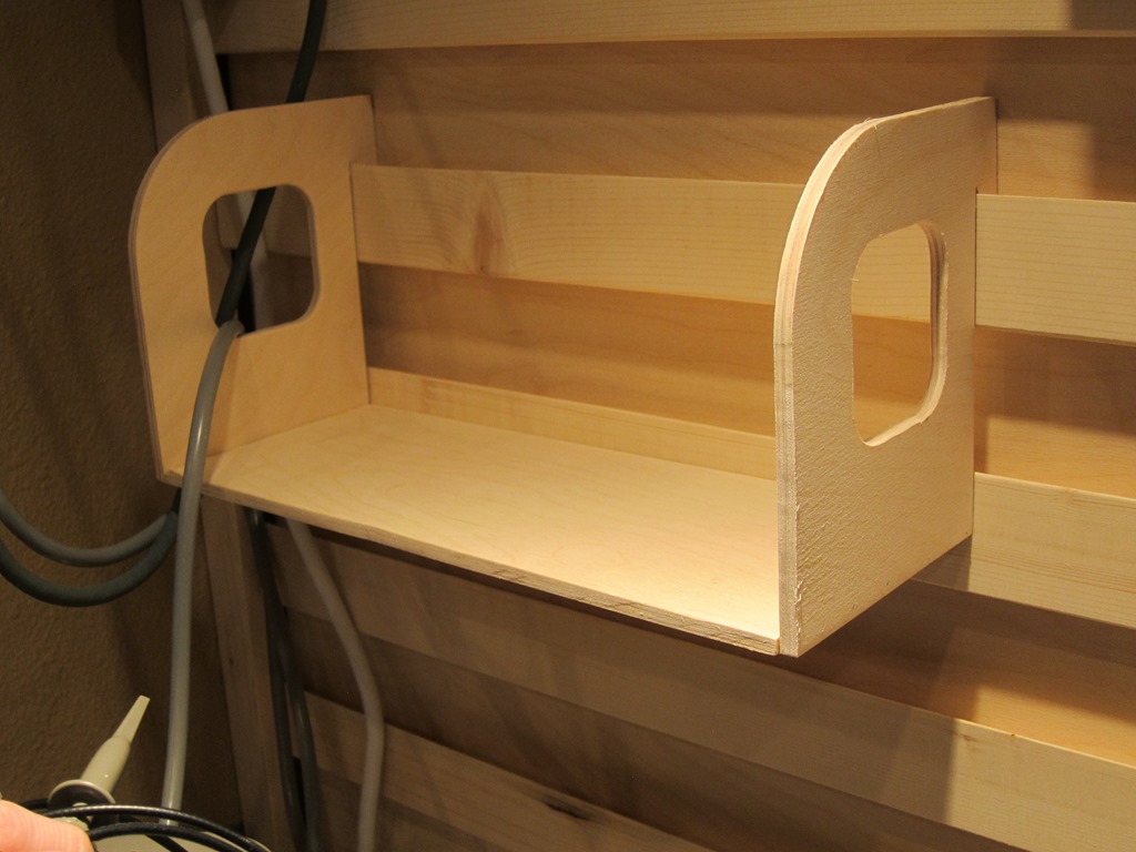
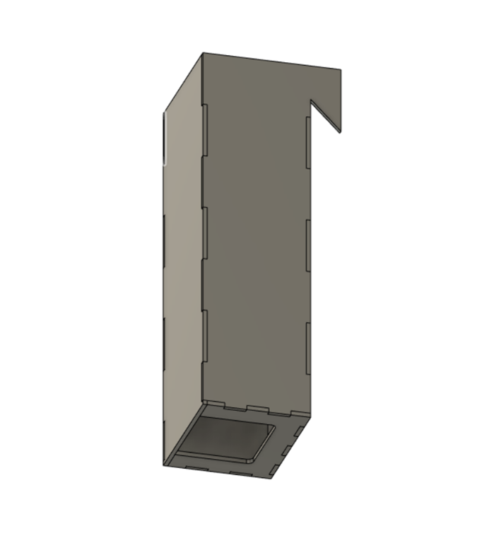
    It’s simple enough that I could have just created a mock-up in cardboard and then used that to create the actual version, but I wanted to play a little, so I did a full CAD design. It was a pretty quick design in Fusion 360 and I’d show you a nice rendered version, but somehow it didn’t get saved along the way. Here’s what the side panel of the shelf looks like; the hole in the end is for the power cord at one end and the cooling fan at the other, and the left part hangs off the cleat:

    Pro tip: The 1x stock you buy may not be exactly 3/4” thick; mine was 11/16” instead. So measure it first; for this shelf I had do sand down the back edge of the cleat.

    image

    The bottom shelf is just that, a rectangular piece of wood between the end pieces.

    As a material I used some 1/4” baltic birch (probably 6mm actually), and I decided to use my Shaper Origin to make the shelf. It is held together with wood glue and some very thin wire pins shot in witn my pin nailer. Here’s the video if you want the details:

    The result is nice and pretty, though I didn’t sweat trying to get things perfect; it’s not furniture:

    IMG_9714

    IMG_9715

    Because of the way the cleats are designed, gravity pulls the mounting cleat both against the wall cleat and the wall plywood, and the back of the shelf presses against the second cleat. It’s surprisingly secure and yet very easy to move around.

    About the time I was finishing this, I said to myself, “Self, that was fun and you made a lot of sawdust, but there’s nothing in that design that you couldn’t have done much quicker and easier with your laser cutter, so at this point I switched tools.

    XBox 360 Power supply box

    When I added a heated bed to my 3D printer, I bought an XBox 360 power supply to power it, and I found that they are wonderful for powering 12V loads; the ones I have provide up to 16 amps of power. So I bought a second one from Goodwill for $4.95 and have used it when I need a hefty supply for testing (like my WS2811 expander which I stress test with 3 50-watt 12v light bulbs). Cheap, compact, and lots of cheap power – what’s not to like.

    Well, I don’t like that it’s cluttering up my workbench, so I’m going to build a box for it.

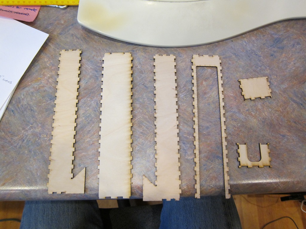
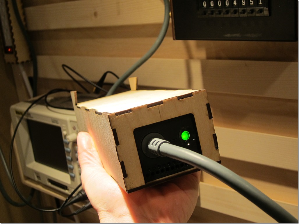
    Here’s the CAD design, the laser-cut parts, and the final result. It’s cut out of 0.10” (2.5mm?) plywood that is strong and easy to cut on the laser (mine’s a GlowForge) and then glued together with wood glue.

    image

    IMG_9707

    IMG_9711

    I measured the power supply with my calipers and it ended up just on the tight side; the power supply slides in but barely. The big cutout for the close end is because there are air holes there.

    The other end of the cable currently just has a set of speaker terminals that accept banana plugs and the enable wires soldered together so it’s always on. Sometimes in the future, that cables going to terminate in a power-supply box with an on off switch.

    The xbox power supply hangs up high. And now I need a place to plug it in as the cord isn’t long enough to reach to the outlet under the workbench.

    Power strip box

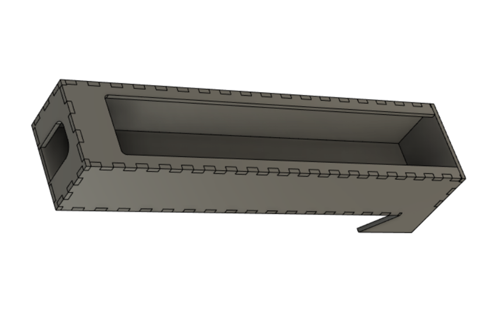
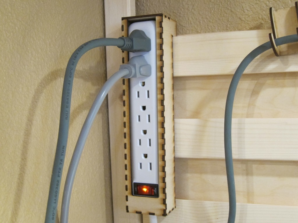
    Another simple box, with the dimensions defined by the size of the power strip that I wanted to use. The design is quite simple with a bit of an assembly caveat; the box has both a top and a bottom so you have to assemble it around the power strip.

    image

    IMG_9713

    Resistor decade box

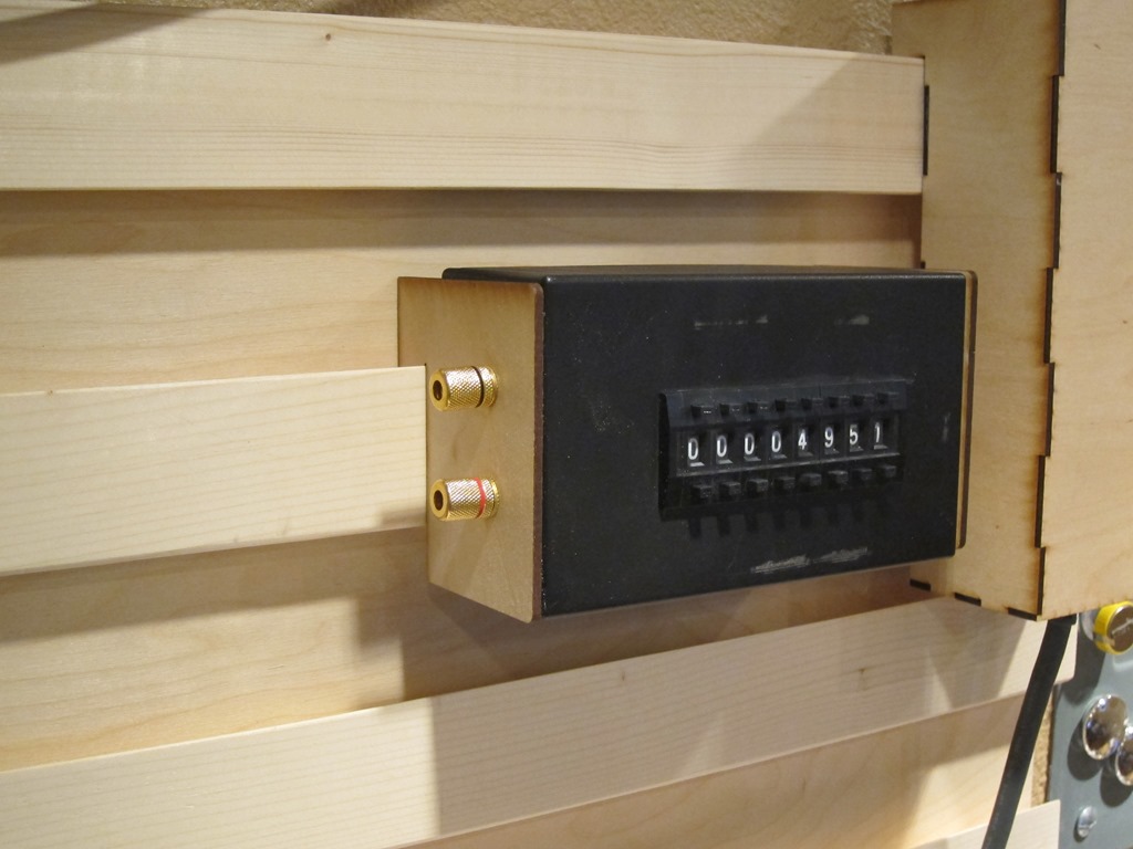
    I built the decade box a few years ago based on this instructable. I do a fair bit of work with LEDs and I often find myself wanting to pick an LED value based either on measured current or brightness. I used to do that with a potentiometer, but it’s much easier to use a decade box.

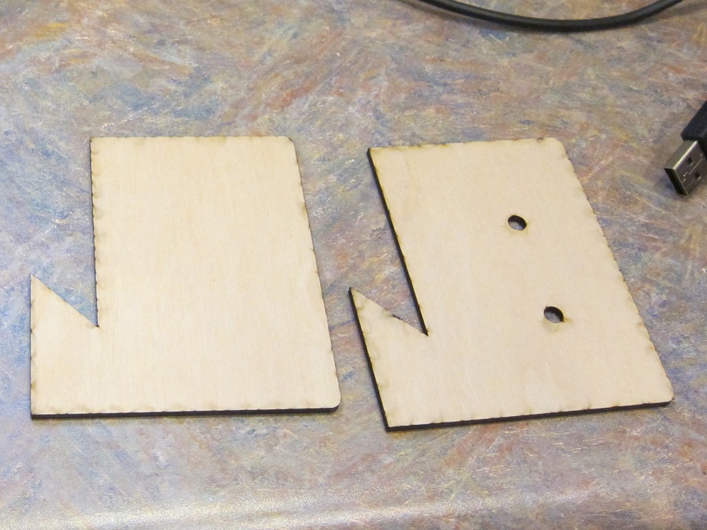
    The design here just has two end hangers; one end is attached using the output posts for the decade box, and the other one is just hot-glued on.

    IMG_9708

    IMG_9710

    You might notice there are some smoke marks on the wood; if I wanted nice I would have masked them off but that was more work than I wanted for this.

    Wire hanger

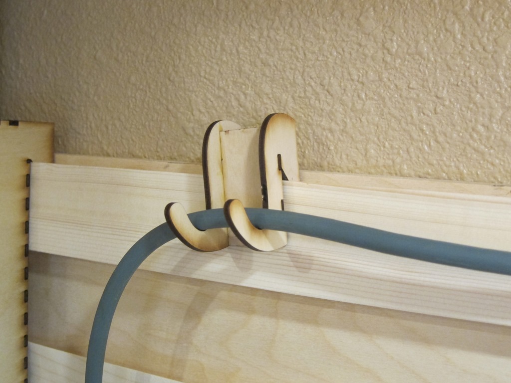
    Just one more design for the first wave; I knew I would have wires running across the board and wanted a way to support them:

    IMG_9712

    A simple three-piece design hold up a power cord. It’s tilted because of the weight of the cord is heavier on one side; I’ll probably do a version with a single hanger in the middle. Or I might cut some one-piece hangers out of 1/4” plywood.

    Video tour

    If you would prefer a video tour of the completed items, you can find it here:


    Power supply hanger

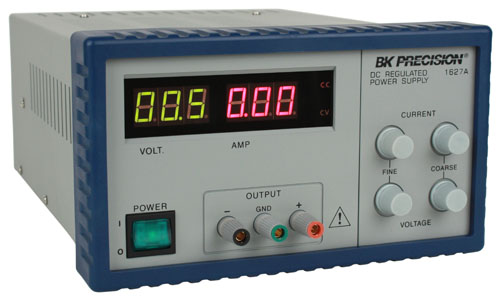
    Model 1627A Right

    When looking at some of the small Chinese power supplies that are out there, I got a line on a nice surplus BK Precision 1627A on Ebay for $55 and ended up buying that instead. I have an older 4 voltage power supply (+12V, –12V, 5V, and adjustable) that I’ve used quite a bit, but it’s pretty rare that I need multiple voltages these days, I already have the hefty 12V, and I’m going to be adding some dedicated 5V supplies as well. I haven’t used +/- power supplies in a long time, so I think the old supply is going to get packed away for now.

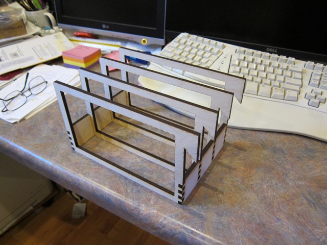
    To do a hanger for this looked a bit more challenging than my previous hangers because this is bigger and it weighs 16 pounds. I did the design and cut it out of 1/4” plywood:

    IMG_9716

    The frames here are about 10” x 7” in size. They are cut out of 1/4” (probably 6mm, actually) and glued together.

    Pro tip: Go back and look at the picture of the power supply picture above. If you look closely on the side and the talk, you will see some screws sticking out. If you measure precisely and cut to that precise measurement, the pretty holder you create will *not* fit over those screws, and you’ll need to remove the screws – and maybe the equipment feet – to get the frames to fit over the item (the power supply in this case).

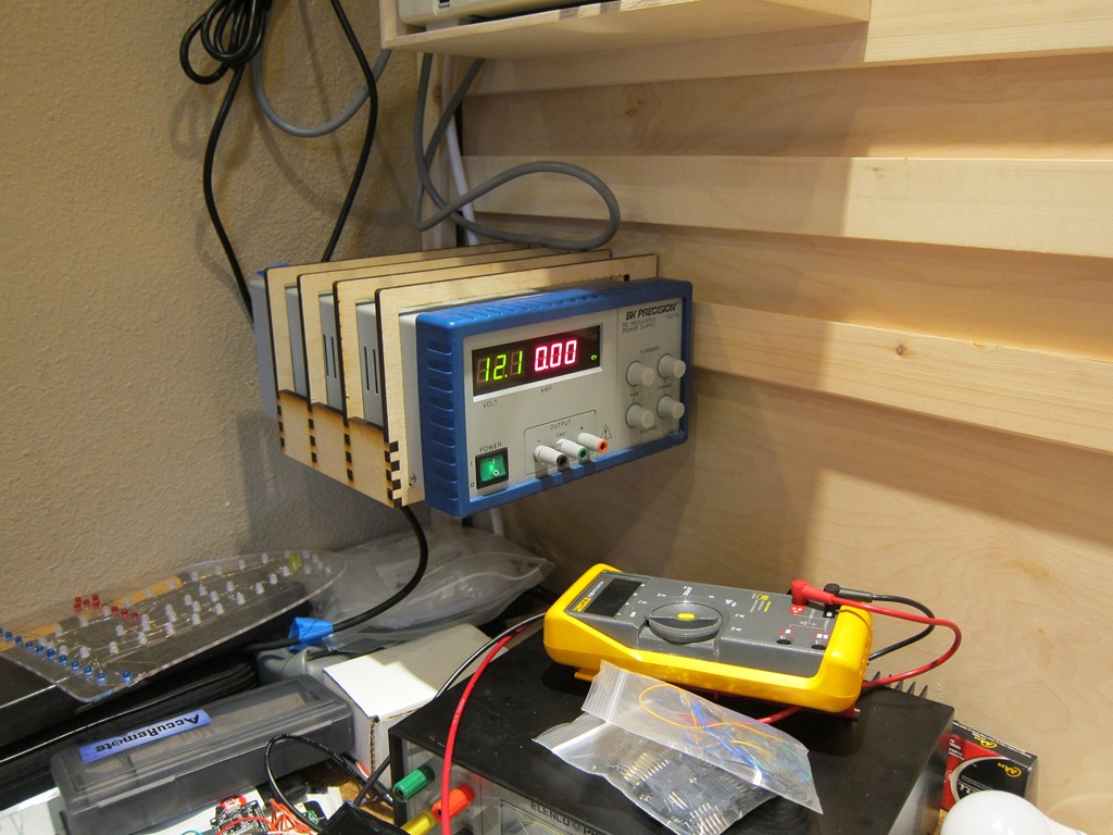
    Not only did I do that, but the first time I put the hanger on I had it on the wrong side, so I had to repeat it. But I did get to the final result:

    IMG_9717

    Futures

    One of my goals was to get my Fluke multimeter off my desk and up in the air, but there are some issues, the biggest one being that the digits are in shadow if the meter is vertical against the wall. I’ve had some designs that put it at the same angle the stand in the base does, some designs that let you modify the angle, and another idea that I might just add some white LEDs to the side so it could be vertical.

    There will be a power supply station close at hand; I think it’s going to support 12V from the xbox supply, 5V both on banana plugs and on multiple USB plugs, and I might integrate one of the cheap chinese boost/buck supplies to give options.

    Finally, there’s the right side of the bench, which has my soldering iron base and my cheap chinese hot-air rework station. I may end up with a cleat wall on that side I can get them up as well.


    What’s up with tip lead?

    I’ve been looking at some skier video recently and I’ve noticed issues with tip lead in some of the better skiers, so I decided to write down a few thoughts…

    Tip lead – also known as “ski lead” – is simply the situation where one ski tip is in front of the other. This is a natural – and desirable – situation at the bottom/end of a turn; as we go across the hill with our weight mostly on our bottom ski, the uphill ski is higher up the mountain. The only way to do that is for the upper foot to be slightly in front of the lower foot.

    How far ahead depends on the degree of slope and the degree of angulation/inclination of the skier. Carving on steeper slopes and with more angulation/inclination will lead to more tip lead.

    All of that is fine. Where we start running into problems is the turn transition, where we go from one turn into the next turn.

    Here’s what I’m often seeing:

    image

    There is a switch in tip lead at the apex. Or, to put it another way, the tip lead at the bottom of the turn persists all the way to the next apex.

    As most of you know, if we want to get a ski to carve, we need that ski to have consistent forward pressure and a tight ankle on that boot.

    Another way to think about this is thinking about which ski is dominant:

    image

    The outside ski that is dominant at the end of a turn is staying dominant into the start of the next turn, where it is the inside ski. It has to stay dominant because the new outside ski is still ahead, which means that it’s not underneath us and therefore not forward weighted. The only way to carve in this state is to carve on the inside ski, which has a number of downsides…

    What I would like to see is for the tip lead to change at the start of the turn:

    image

    That gives the following result. To label it:

    image

    I want the right ski dominant throughout the turn to the left and the left ski dominant through the turn to the right. That is what will give me those nice, early entry, flowing carves.

    How do we accomplish that?

    Different people have different cues that work for them; for me I’m thinking of actively pulling that uphill ski back and standing up on it. Others think of using the hamstring and glute to pull the knee back. And others think of it more as a pressure change.

    One more picture:

    image

    On the left side, we are at our turn finish. Our weight is mostly on the downhill ski, and our uphill knee is bent and the ski is forward.

    At turn initiation, we have actively gotten our uphill (old inside) ski underneath us, and we are lessening the amount of pressure on our downhill (old outside) ski. That lifts the weight off of our downhill ski, and helps our upper body move – or “flow” is the term I usually use – downhill. That movement lets us get our skis on their new inside edges at transition and carve both into and out of the turn.

    Hope that helps. Please comment with any questions.


    An ESP-32 Remote Control–Introduction

    A couple of years ago I did an ESP-32 based controller for our landscape lights and fountain. It has a nice web-based interface, if you like the way interfaces looked when HTML was young…

    image

    In addition to this web page, you can hit http endpoints directly, so you can control things with either a browser or an HTTP app on your phone. It’s a bit of a pain to dig your phone out and run an app to turn on lights, so I’ve always planned on doing a handheld controller. It’s going to be pretty simple; just a set of buttons and an app that sends requests to the actual controller.

    At least, that’s how it started…

    My original plan was to use an ESP8266 because it’s smaller and to use some normal momentary pushbuttons:

    Momentary-ON-OFF-Push-Button-Switch-Waterproof-12mm-Black-M122-Mini-10pcs

    That would have been fully functional, but I didn’t really like the way the buttons looked and I didn’t like the low-power options very much. I was looking through the ESP-32 technical manual and remembered that the ESP-32 has a touch-sensor subsystem that supports 10 separate inputs. That means I can do a cleaner-looking controller that has metal touch points rather than buttons, and the ESP supports wake on touch, so I can put the controller into deep sleep.

    Conceptual design

    Here’s a very quick drawing:

    image

    Here’s what I’m thinking for the design. There are 5 circuits to control:

    • Fountain pump
    • Bed lights
    • House lights
    • Umbrella lights (strips under umbrella)
    • All lights

    In addition, I want to be able to control the brightness of the umbrella lights in 5 steps; 20%, 40%, 60%, 80%, and 100%

    Coincidentally that requires 10 different controls, which is exactly how many touch inputs the ESP has, so that worked out well.

    The controller will be remote-control-shaped, with batteries (tentatively 2 AA alkalines) near the bottom, the ESP in the middle, and an array of touch points at the top.

    Sleep battery calculations

    There is an assertion that the ESP32 in deep sleep only pulls 2.5uA. A typical alkaline AA cell has a capacity of about 2000-3000 mAH, so if we do some math:

    Hours = 2000 mAH * 1000 (convert to uAH) / 2.5 = 800,000 H, or 33,000 days. If we could really get that, that would be 91 years on standby.

    Let’s do the calculation the other way; if we wanted batteries to last a year, that would give us:

    2000 mAH / 365 = 5mAH per day, or 228 uA of constant current. If I can hit something under that, I’ll get a year out of the batteries.

    Getting that to work is going to require me to either modify the ESP-32 devkit boards I’m using or switch over to a raw module and separate programmer, but that’s a matter for another post/video


    Pages:1234567...35