XBee Landscape lighting project – Software

The software is all written in C using Codevision AVR, a pretty nice C compiler. It has a very nice wizard that lets you say that you are running your chip at 8MHz and then allows you to set (for example) the timer1 refresh rate to by 52000Hz from a pulldown menu rather than knowing that you need to set a specific register to a specific value. It also writes the shell of your interrupt servicing for you. Oh, and it knows what AVR microcontrollers support which features, so it won’t let you configure the chip to do something it can’t.

The only place where it falls down is setting the fuse bits (burned in settings for things like clock speed, whether you use the internal/external clock, and some pin assignments), which it just labels by name. For those I use AVR studio, Atmel’s free development tool. If you want to go this route there is a version of GCC that you can use.

For the base station, all of the important operations are handled in interrupt code – the main loop just loops endlessly.

Timer1 code

The timer code runs at 10Hz. We get there by the following:

The timer rate is set to 31,250Hz. Since I’m looking for 10Hz, I need a base frequency that is evenly divisible by 10. The timer is set so that an interrupt is generated whenever the timer overflows (ie goes from 0xFFFF to 0x0000). We need this to happen every 3125 counts, so we set the initial value to 0xFFFF – 0x0C35 = 0xF3CA. That gives us the heartbeat.

Here’s the code:

interrupt [TIM1_OVF] void timer1_ovf_isr(void)
{
        // Reinitialize Timer1 value
    TCNT1H=TCNT1H_VALUE;
    TCNT1L=TCNT1L_VALUE;

        // read the buttons from the remote, and turn on the output channels as necessary.
HandleButtons(); if (timeRemainingTicks > 0) {
// In the last 5 minutes, blink the lights off for 1/10th of a second every minute. if ((timeRemainingTicks % 600 == 0) && (timeRemainingTicks <= 3000)) { PORTB = 0; } else { PORTB = outputState; } timeRemainingTicks--; } else { outputState = 0; PORTB = 0; }

        // every second or if the state is changed, we send out the heartbeat over the serial link.

ticks++; if (outputState != outputStateLast || ticks == 10) { SendOutputState(); outputStateLast = outputState; }
        // every second we blink the led for 1/10th of a second
    if (ticks == 10)
    {
        ticks = 0;
        if (outputState != 0 && timeRemainingTicks > 0)
        {
            STATUS = 1;
        }
    }
    else
    {
        STATUS = 0;
    }  
}

Serial port code

The interrupt handler is simple:

interrupt [USART_RXC] void usart_rx_isr(void)
{
    char status,data;
    status=UCSRA;
    data=UDR;
    if ((status & (FRAMING_ERROR | PARITY_ERROR | DATA_OVERRUN))==0)
    {
        HandleChar(data);
    };
}

char state = 0;

void HandleChar(char c)
{
    switch (state)
    {
        case 0: // ready;
            if (c == 'S') state = 5;
            break;
            
        case 5: // 'S'
            if (c == '1')
            {
                AllOn();
            }
            else if (c == '0') 
            {
                AllOff();
            }
            state = 0;
            break;
    }
}

HandleChar is an implementation of a finite state machine – it looks for “S0” or “S1” and performs the appropriate action.

Remote Code

The remote uses the same timer approach as the base station.

// Timer1 overflow interrupt service routine
interrupt [TIM1_OVF] void timer1_ovf_isr(void)
{
        // Reinitialize Timer1 value
    TCNT1H=0xF3CA >> 8;
    TCNT1L=0xF3CA & 0xff;
// The timeout is set to 20 ticks. If two seconds go by without
// getting a heartbeat from the base station, we turn off the link LED
if (linkDetectedTimeout > 0) { linkDetectedTimeout--; LED_LINK = LED_ON; } else { LED_LINK = LED_OFF; LED_LIGHTS = LED_OFF; currentLightState = 0; }

// Set the light LED based on the current light state if (currentLightState == 1) { LED_LIGHTS = LED_ON; } else { LED_LIGHTS = LED_OFF; }
// If the button is pressed (and it's newly pressed),
// send the appropriate on or off command. if (BUTTON == 0) { if (!buttonPressed) { buttonPressed = 1; if (currentLightState == 1) { SendString("S0"); } else { SendString("S1"); } } } else { buttonPressed = 0; }
// Flash the power LED on for one cycle out of 10 tenths++; if (tenths == 10) { tenths = 0; LED_POWER = LED_ON; } else { LED_POWER = LED_OFF; } }

Serial port

void HandleChar(char c)
{
    putchar(c);
    switch (state)
    {
        case 0: // ready;
            if (c == 'E') state = 3;
            break;
            
        case 3: // "E"   
            if (c == 'G') state = 4;
            else state = 0;
            break;
           
        case 4: // 'EG'
            if (c == '1')
            {
                SetLightState(1);
                LinkDetected();
            }
            else if (c == '0') 
            {
                SetLightState(0);
                LinkDetected();
            }
            state = 0;
            break;
    }
}

Another finite state machine. Whenever it gets “EG0” or “EG1”, it sets the link timeout and the appropriate light state.

XBee Landscape lighting project – Hardware

I’ve finished my landscape lighting project, and thought I’d share how it came out.

I had a few requirements:

  1. I wanted to be able to turn on and off the lights from out where the lights were (some 150′ from the house) so we could have light when we showed up at night.
  2. I wanted the lights to turn off automatically after 2 hours if they were accidentally left turned on.

My first design was pretty simple – I would put pushbuttons out with the lights and do a simple program for an AVR microcontroller to detect the pushbuttons and handle turning on and off the lights. That hit a couple of snags.

The first was a physical one – putting physical pushbuttons out meant that I’d have to run about 700’ of signal wire, build waterproof boxes to hold the pushbuttons, mount them on the trees, etc. That was a fair bit of extra work, and not the fun kind.

The second was a bigger problem. Sensing physical pushbuttons was insufficiently challenging and interesting.

So, a V2 design was born. I had been looking for an excuse to do something with some of xbee radio modems, and I decided to use the xbee pro modems for the project, since they are higher power and longer range. These are really cool devices which, in their default mode, act like a virtual serial cable. You send characters into the modem at one end, and the same characters come out the other end. It will do this at up to 250kbps and a maximum distance of a mile (your mileage may vary. Actual mileage will probably be less). You can do a lot more sophisticated stuff with it (meshes, repeaters, etc.) in the advanced modes as well. The modems also have some built-in analog->digital conversion and digital I/O circuitry built in, but since you need a microcontroller to drive it I don’t see a ton of use for that in most applications (though it might be useful in some pc connected applications).

If you are building something that is xbee-based, I highly recommend getting one of the usb adapter boards like the one from sparkfun. It is really useful to send command from the PC, and you can use putstring to write debugging information back to the PC.

After a fair bit of experimentation, I ended up with the following scheme:

The base station sends out a status heartbeat every 1/10th of a second. It also handles the status led, any button presses on the wired remote, and timekeeping. Separately, it also handles any on/off command that come in over the xbee.

The remote receives the status heartbeat, and uses that to turn on the link led (lighted whenever the status heartbeat is received), and set the light status either on or off based on the current status of the lights.

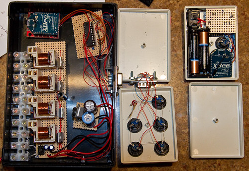
Time for some pictures. Click on the picture for a bigger version that has the parts identified.

The big black box on the left is the base station. To the right of it is the wired remote, and on the far right is the wireless remote.

I should note that everything here is hand-wired. It’s not what you would call neat, but it is simple to do and functional. The thin wire that you see is 30 gauge wire wrap wire, which is more than enough to carry digital signals. When I’m hooking it to discrete components (caps, resistors, leds, etc.) I use my cheap wire-wrap tool and wrap the wire around 3 or 4 turns, and then solder it. This makes it easy to hook the wire up so it doesn’t come off while I solder it.

We’ll start with base station.

In the upper left is the xbee pro radio modem sitting on top of a sparkfun adapter. The sparkfun adapter gives you easy access to all the pins, but the only reason I used it here was because it does the conversion between the 5v that the attiny is using and the 3v that the xbee wants. I could have done it all at 3v, but I didn’t think about that option until I had already put in my last order for parts in.

Below that is the relay board. It has 4 channels (I added individual channels addressable from the base station). Each channel features a 5V relay that switch the 12VAC that the lights use. I’m not a big fan of relays – for AC either using solid-state relays or triacs is generally simpler, but 12VAC is an odd beast and nobody builds a lot of designs for that, so I went with the relays. The downside of the relays is that they require a fair bit of current – about 200mA each. That will cause a bit of an issue later. Each relay is driven by a dedicated transistor, since there’s no way the ATTiny can push 800mA through it. The transistors are NPN power transistors in TO220 packages, which are a bit more rugged than the small ones in case I needed to dissipate a bit more heat. The relay board is the the least optimal part of the design, since it requires a 5V power supply that can put out a lot of current. A better approach would have been to use relays with 12VAC coils, and then drive the coils with some small triacs – that would have reduced the power supply requirements way down. If I had built that power supply up front and tested it driving 4 relays, I would have found that out, but I drove it from my bench supply instead. At the bottom of the relay board is where the 7805-based power supply lived originally, which worked but put out way too much heat.

To the left of the relay board is the terminal strip to connect the lights, and the 12VAC input at the bottom. This sticks through a slot cut in the side of the box.

To the right of the relay board is the switching power supply. I could have built one myself using the popular lm7525, but to make things simpler I ordered a prebuilt one. There’s a hefty 2200uF capacitor on the input from the board to smooth out the rectified 12V from the full-wave bridge on the relay board, and then a 470uF capacitor to smooth the output of the 7525. That gives me the power I need to drive the relays without too much heat.

Finally, on the right side is a DB9 (aka “old-school serial port”) connector. In my current installation, the base station will live close to the wired switches, but will eventually move to an outbuilding. At that point I can just pull some cat5 wire and add connectors to hook the base to the wired remote. To the right is the wired remote, which couldn’t be simpler – there are 5 pushbuttons and a status led, some wire, and a DB9 connector.

On the far right is the wireless remote.

In the upper left is the power switch. I went with a hardwired switch because the remote will likely rattle around in a glove compartment, and I was worried that any button-press approach would be prone to accidental activation. Below the switch is two AAA batteries, which gives me the 3V that the remote runs on. To the right of that is the xbee pro module, with 4 wires hooked to it – +3V, ground, transmit, and receive. Above that is the on/off pushbutton. Finally, lurking at the top-right is the bottom of the board that holds the attiny2313 – it’s upside down because the status LEDs are underneath the board on one end, and if it was the other way it would be likely to short out.

Here are the assembled remotes:

On the left one, we have the three separate channels on the left, all on/all off on the right, and status at the top. The wireless remote has the pushbutton, on/off switch, and 3 status leds. The top led is power – it is on for 1/10th of a second, off for 9/10ths of a second. The middle led is link status (on =  linked), and the bottom is the light status (on or off, in case you can’t actually see the lights).


Sports shooting #8 – Evening and night games

My first year or so, I was shooting my daughter’s lacrosse team, which played on weekend afternoons. Then, when my daughter entered high school, she switched to playing games that are in the late afternoon, early evening, or night. There are significant challenges to shooting these games, and there are some weird things that can happen that are very confusing.

This is where it gets expensive. My first year I was shooting with my Rebel XT and 70-200mm F4L, and in most of the games I was done by halftime because there simply wasn’t enough light to be able to get any decent results. I upgraded to a 40D and the F2.8 version of that lens, which gave me about 2 more stops, which is the difference between 1/800th (tolerable), and 1/200th (not even close). This year I just upgraded to a 7D, which should give me another stop, perhaps 1.5 stops.

And I’m sure I’ll still be complaining that I don’t have enough light. It’s just really hard to get the kind of results you can get during the day. Though I will say that having the equipment that lets me be functional at night provides much more flexibility during the day – instead of being stuck at F4 @ 1/800th, I can go to F8 or shoot closer to 1/2000th if I want to.

I like to think of these as three different environments, though you may get all of them in a single game.

Last afternoon (before sunset)

There are a few obvious things here. As you get closer to sunset, you are going to have to deal with less light. If it’s cloudy, you will start with less light but it will generally hold up a bit longer, while if it’s clear the light can go off really quickly. Consider shooting shots during warmup, and try to get a lot of the action early, especially if your gear doesn’t do well in low light.

You will generally want to shoot with the light source at your back, though sometimes you may want to break the rules:

This is shot almost straight into the sun, and then I used a fair bit of fill light in lightroom to bring out the players. If you look at the original, it’s pretty noisy, but it works well in B&W, and I like the outline of the sun in the hair.

This time of day does encompass the golden hour, and sometimes you get lucky, and the sun gives you perfect lighting. Not only is it nice and warm, but it can get inside helmets or headgear because of the angle.

Dusk/Twilight

At this point you are either contending with rapidly waning light or a mix of natural light and artificial light. The light will be changing pretty rapidly, so you may need to play around with your ISO settings often. The color balance may be weird, as the light from the sky will be very blue but the artificial lights usually aren’t quite as blue so it can be hard to get colors that look decent.

Artificial lights

Artificial lights are designed to make sports at night possible. They are not – unless you are lucky enough to be in a college or pro stadium where they do TV – designed to make photography work well.

There are a few things that you may have to deal with, in addition to the lack of light:

You can’t see it, but the majority of stadium lights pulse at 120Hz – they go on and off 120 times per second. If your shutter happens to open while they are off, you don’t get any light. To improve this, many places use what is called three-phase power. Instead of one set of lights that go on and off every 120th of a second, you break the lights on each pole into three groups, with the second and third group each delayed a bit from the group before. So, you never have a time when all the lights are out.

Unfortunately, this sometimes doesn’t happen. Sometimes a whole pole will be on one phase, so you may get pictures where one part of the field is lighted and the other isn’t lit at all. If this happens where you’re shooting, you have my sympathy – short of getting the lights rewired, there’s no fix.

Even with correctly wired lights, you still have the problem that during each cycle the lights heat up and cool down a bit and the color temperature shifts.

Alternatives

If you can’t get a decent shutter speed with your equipment, there are a couple things you can do. Some photographers shoot with strobes. To do that you would need decent power from the flash, a subject that’s close, and approval from the coaches.

What I do is turn the iso down and get the shutter speed into the 1/10th of a second range, and pan. You can get some nice abstract shots with this.


(12 – 5) x 0.850 = ouch

I recently finished the construction on my landscape lighting base station, putting everything into the boxes I have, and wiring everything up.

Turned the power on, pressed the buttons, and the relays worked fine. Turned on the remote, and it worked as well. Win.

And then I did the important heat test, where you grab the components to make sure that they weren’t overheating. The relays were fine, the transistors driving the relays were cool, and the avr was also cool.

Then I burnt myself on the 7805 voltage regulator. Which isn’t very surprising. The 4 relays pull about 750 mA in total, and along with the xbee and everything else, the total current draw is 0.85 amps. The regulator itself is rated up to an amp, so it’s fine, but since the input voltage is 12V, that means we need to get rid of (12Vin – 5Vout) * 0.85A = 6 watts. Not a ton of heat, but waaay too much for the regulator by itself. I dug out the data sheet, and found that the 7805 is rated up to 125 degrees C at the junction which is pretty darn hot. I modded a heatsink into the side of the case, hooked it up, turned everything on, and let it bake for a bit. My IR thermometer says that the heatsink stabilizes at about 74 degrees C. This is okay for the device, but hot enough that you don’t really want to be touching it.

So, I’m thinking about the option. There are really two that I’ve considered…

The first option would be to rework the output board. If I had been thinking ahead of time, I would have used 12VAC relays, driven then from triacs with opto-isolators that connected to the AVR. That would have dropped the per-channel current down to perhaps 24 mA, and the overall current to perhaps 200mA. But that’s still going to dissipate over a watt, and still require a heatsink – though it would be a lot cooler.

The better option is to switch to a switching regulator. Those run at high enough efficiency to not need a heatsink, and they come in drop-in replacements for the 7805. A bit pricey, but certainly a simpler choice.


Light progress

Lots of progress this week.

After teaching skiing all day Saturday, I went back to the cabin and wired up the lights in two places. I had bought some outdoor wire nuts that are filled with silicone, but they turnout not to work well at all and to be exceedingly messy. I ended up using crimp-on connectors (yellow), which should work okay in the weather if they’re crimped well. After it got dark I went into my shed and hooked up two lights there, 20 watt auto lights just hanging from the rafters.

In the morning we were tired, too tired to go skiing, so I went out and measured the voltage on each of the away locations, and found that they were both at about 8.5 volts. I moved that circuit to the 15V tap on the transformer, and then wired up the middle-distance lights, and switched them to the 14V taps. All of them look much more like halogens now.

When I got home, I finished the base station code by adding in a status light, and then started on the code for the remote. It was pretty simple, and only took a couple of hours – I was able to adapt the code that I wrote for the base station.

And now for the real test – could the remote talk to the base station? I breadboarded up the remote and got it working talking to the second xbee on the PC, and then hooked up one Xbee to the base station and the other to the remote. After remembering to reverse the transmit/receive pins, it fired up and worked first time. Press the button on the remote, the lights toggle on the base, and then the status light on the remote switches as soon as it gets word back from the base station.

I took a little trip outside, and found that the remote could still get a signal for from the base about 200′ or so away from house. That’s pretty good considering that my workbench is in an office that’s mostly underground. It’s also possible that the antenna orientation is sub-optimal – there’s a short antenna attached to the module but it’s currently flat against the module, which may compromise the dispersion pattern.

I lost control over the lights at about half that distance. I think the jury-rigged diode-drop power supply for the xbee didn’t give enough current for the remote xbee to transit consistently at full power. In the real version of the remote I plan to run everything on 3 volts from the battery, and that should work a bit better.

I’m also going to speed up the frequency of the updates that go from the base to the remote – right now they only go at 10 Hz, and sometimes there’s a noticeable delay between when the button is pressed and when the light shows up.

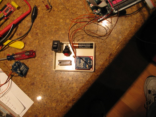
Here’s a picture of the breadboarded remote and the base station. Click on it for a Flickr view with some more information.

I did some test fitting of components in the case I got for the remote:

Fit test for remote components

I thought it was going to be too tight, but I think i will probably be fine. 

I really like microcontrollers – it takes a while to do the code but the discrete component count is so much smaller.

Remote bill of materials:

  1. Attiny2313v
  2. 2 AAA batteries
  3. Battery holder
  4. on/off switch
  5. momentary pushbuttons
  6. 3 leds & dropping resistors
  7. xbee pro module
  8. Case/wire/etc.

Base bill of materials

  1. 3.3V regulator
  2. Bridge rectifier
  3. 2 – 10uf filter caps
  4. attiny2313v
  5. xbee pro module
  6. 5 momentary pushbuttons
  7. 1 led & dropping resistor
  8. 4 relay sections (5V 30 amp relay, transistor, 2 resistors)

Landscape light update

I’ve been pretty busy with skiing, but have made some good progress. I’ve played around a bit with the available commands, and have made a few decisions.

First, I’ve decided to use the xbees in their simple serial replacement mode. In this mode, it just acts like there’s a serial cable between the two modules. The more complex stuff looks interesting for future stuff.

Second, I’ve figured out what I want to do to handle the handshake between the two devices and how to structure the code. I’ll share some code when I get it written.

Base station:

  1. The main loop will constantly send out a heartbeat with the current status of the lights. It will send “EG0” if the lights are off and “EG1” if the lights are on, at an interval of 1 second. I’ll either do the loop with a simple delay routine (delay_ms() from the standard library), or I’ll piggyback on the short-period timer that I’ll use to debounce. Probably the former.
  2. The interrupt service routine for the xbee will look for commands and process them. If it sees S0 it will turn the lights off, and S1 it will turn the lights on.
  3. The interrupt service routine for the pushbuttons (“all on”, channels 1-3 on individually, “all off”) will handle servicing the buttons. I’ll probably use the short-period timer to debounce the pushbuttons
  4. The interrupt service routine for the long-period timer will handle turning the lights off after a time period.

That’s going to use up most of the capability of the 2313 I’m using. I decided to do 3-5 output channels, each with a dedicated 30A relay to do the actual switching. The relays will be driven off of the avr using a transistor to get the necessary current, which is something like 200mA, far more than you can get from an AVR.

The xbee unfortunately runs on 2.8-3.4V, not the 5 volts I bought for the power supply. The adapter boards that I bought down-regulate the voltage, but I don’t want to waste them on a project like this. I could put a nice 3V regulator on it if I have it, but I’m thinking of just putting three silicon diodes in series, which would give me 0.65 * 3 volts – almost perfect – and it will work fine assuming I don’t pull too much power through them.

Remote station:

This one is going to go in a tiny project box, which an on/off switch, a link LED, a status LED, and a pushbutton. I’m going to fit all that into a tiny project box, along with two AA alkalines (or maybe AAA if I don’t have the space).

The code will be something like the following:

  1. On startup, blink the link LED a few times.
  2. On the interrupt service routine for the xbee, look for the EG0 or EG1 data. If it’s there, turn on the link LED, and turn on the status LED if the command was EG1. Set the short-period timer for about 900 mS.
  3. On the short-period timer interrupt, turn off the link LED. This will have the effect of blinking the link LED off for 100mS as long as the remote is receiving data from the base station.
  4. I’ll use the long-period timer to debounce the switch. On that interrupt I’ll send S0 if the current status is on, and S1 if the current status is off.


Lights

I mounted three sets of three lights on trees over Sunday, so this weekend I’ll be able to wire them up to the transformer and see what voltage I need to use for each zone.


Ski Instructoring – Day 2

Yesterday was day 2 of the 2010 ski lesson season.

We got up there early, and I found that my cadet Rosemary (not her real name, in case you haven’t figured it out) fell and hit her head while skiing during the week. She’s fine, but is out for the season. A few other things changed (not unusual early in the series):

  • My missing student “M” would be coming up this week. According to the email that I saw, she had skied hogs before but wasn’t really a big fan of it (sounds like parents taking her up a bit before she was ready).
  • My lower-ability student “H” would be dropping down to a lower class
  • I was getting another student (“Z”). He had been riding Daisy before but I don’t know much more than that.
  • I have a new assistant to help me (we’ll call him “Lemont”).

Not to bore you with details, but we did one trip up daisy and then two trips up hogs, with a play-in-the-snow break in between the two runs. My goal for right now is mostly around mileage – we’ll do a little on technique (wedge-christie and up/down), but mostly I’m just looking for mileage.

In the afternoon I got two first-year kids and took them on a couple of trips on daisy. That also went well – I spent a lot of time skiing wedge turns backwards so that I could show them the path that I wanted them to follow and make sure that they were turning out of the fall line on each turn (they need that to be able to progress to steeper slopes). My legs were more than a bit sore after that.


Ski Instructoring – Day 1

Last year my family decided to try the ski instructor thing, and spent the year as cadets for Olympic Ski School. We’d taken lessons from Oly for a long time, and after topping out in their classes got asked to try teaching.

This year, we all have classes on our own. I have a class of level 1.5 kids – 4 and 5 year olds.

PSIA (Professional ski instructors of america) uses a 9-level scale to classify skier ability. Level 1 skiers have never skied before (or, perhaps, have only been on skis a few times).

The kids in my class have been on skis a bit but aren’t quite up to a level 2 class. This isn’t surprising – 3 and 4 year olds don’t have a lot of coordination and may not be able to progress too much in their first year.

I have 5 kids scheduled in my class, and a cadet (who I’ll call Rosemary) to help me. Four of the kids show up, we put on our skis and shuffle out to the beginner area.

This will be the first test of the 4 days of clinics that I did in early December. I worked with a great instructor last year, and after a lot of experience teaching other things, I don’t tend to get very nervous.

My first task is to assess the class. I talked with all the parents before hand and from my discussion with them, all the kids should be at a roughly compatible level, but parents often don’t do a good job of matching their kids to the description in the ski school pamphlet. All the instructors will do this and determine whether we can shuffle students around to better equalize the skill level in classes.

I watch the four kids shuffle over to the beginner area. This is the first evaluation step – you can tell a lot about how comfortable the kids look with these weird heavy things attached to their feet.

We start with a straight parallel run down a slope that is just steep enough for them to go forward. They look fine doing this. Next we send them down and ask them to do a few turns. E, J, and A do these turns well, but K says that he doesn’t know how to turn. We talk with him a bit (hard because he’s not very talkative right now), so Rosemary says she will work with K while I take the rest up the magic carpet (aka “conveyer belt”). If they do well enough on this we’ll head up the chair lift. They do nice wedge turns coming down the steeper part of the magic carpet, and my evaluation is that they’re good enough to do daisy. As the last one comes down, one of our level III instructors comes over and says, “take them up Daisy”. We talk a bit about K and he goes over to give Rosemary a hand (it’s a bit hard to start that way as a cadet).

We end up taking two trips on daisy during the remainder of the lesson. We’re working on linking turns, and we start moving into the next part of the progression – doing straight runs (“french fries”) across the hill, and then wedge (“pizza”) for the turn.

Next week, we’ll spend some time working on vertical motion, and starting that vertical motion by standing tall on the uphill ski. This will help the uphill ski start carving around the turn *and* unweight the inside ski, so that the kids will start being able to match the inside ski to the outside ski as part of the turn.

It was a lot of fun and a nice challenge to do this – I stopped coaching soccer when my daughter entered high school, and I’ve been missing that sort of interactions. The kids are a kick and I enjoy being silly with them.

Late in the lesson we had to stop for a bathroom break (not uncommon in this age group), and then headed in for lunch. I was originally scheduled to have the afternoon off, but I ended up getting a second gig – I’m assisting with my wife in the afternoon of her 4-hour level 1 class. We spent a couple of hours working with kids on the magic carpet – a lot of running around in ski boots and picking kids up.

Then we spent an hour or so at a preparation clinic for our upcoming level 1 instructor test in February.

We skied a few hours Sunday morning, but didn’t last long. We are really tired.


2009 Cycling Summary, 2010 Preview

I finally imported all my Polar data for last year (complicated because my new laptop doesn’t have an IR port, so I need to go through my old laptop), so here are my stats for the last year.


2009

2008

Distance

2253.3 miles

1578

Rides

84

75

Time

150:24 hours

110:41

Average speed

15.0 MPH

14.8

Elevation Gain

109777′

80459

Calories

81273

66333

Min temp

33.8 (12/3)

37

Max temp

95 (RAMROD)

84

Overall, the year was pretty good, featuring both Livestrong and RAMROD. About 50% more mileage than 2008, though I probably spent more time on my rollers in 2008 than 2009, and that doesn’t show up.

To work on strength I spent the bulk of my rides on the middle ring of my triple, which makes my smallest gear a 39/27. That was pretty painful on group rides when we hit slopes that are 10%+, but it did make a significant difference in my strength during the summer. I did drop down to my 30 on the front on the 7 hills of kirkland, livestrong, and ramrod.

Next year, my plans are to do 7 hills (the full century version), and then repeat on livestrong and ramrod. I also plan on skiing more so my mileage in the early months may be low – I hope to play some soccer during the week to compensate.


Landscape lights V2.0

I’ve taken a new approach with my landscape lights.

To recap, I needed a system that had remote on/off from a few (2 or 3) locations perhaps 150′ or so away from the transmitter. My plan was to do a simple remote pushbutton system, and then to run two runs of wires out to the remote locations – 12VAC for the lights, a second pair of wires for the pushbutton.

I bought the main wire, and at about $0.30/foot for 12 gauge, that was $150 in wire for 500′. I spent some time looking for all my local sources, but nothing I could find was much less than $0.30/foot, which would mean at least another $100 to get to those two locations. Plus, while the main wire was rated for outdoor applications, I was having trouble finding something thing (say, 25 gauge) that was outdoor rated, and I was concerned that it wouldn’t last very well running from here to there through the woods. Not to mention the pain of running two lines over one line.

So, I needed a way to get rid of the cable. My first thought was to do some sort of higher-frequency signaling over the main power line, but a) I don’t know a lot about that area, ii) I don’t want to know more about that area, and 3) the X10 folks had a fair bit of trouble getting it to work reliably. If I went that direction, I could put in a whole lot of work without getting something that worked reliably, which would be more than a bit annoying.

The second option I considered was wireless. I dug out some links I had kept, and once again came across the xbee stuff. At something like $20 per node, I could build a base station node + 2 remotes for less than the cost of the wire. After a bit of though, I decided to build one base station node and one remote that will live in the ski car. I also decided that I would probably go with the XBee pro implementation for the extra range, as I’m at the limit of where the normal xbee stuff works reliably, and the place I plan to mount the transformer may not be the best location for radio. The pro nodes are a bit pricier, but it will still be a wash compared to cable and I have a couple of other wireless projects in mind.

Granted, this will be a ridiculous amount of overkill. I’m going to use a full-duplex 256Kbit link to send simple on/off commands. I thought about using some of the other wireless approaches out there that are a bit cheaper, but I think the XBee will work well for a couple of other projects that I’m considering, and I’d rather bite off that part once.

You can get the xbees from a few places. I ended up ordering mine from SparkFun, two XBee pros, and then a couple of breakout boards – one USB one, and one simpler one. I also ordered a new transformer, which is a fair bit nicer than the previous one, and has the added advantage that it, like, works. Last weekend, on my last day of vacation, I hooked plugged each of the xbees into the USB, ran X-CTU, and upgraded them both to the newest firmware.

Last night, I dug out an ATMEGA16 processor, put it in the programmer, and started writing code. I chose that processor because it’s the only one that I have right now that supports USART serial, and I wanted it to be serial. Put it in the programmer, got things running, and wrote some code to put the XBee into command mode “+++” (the xbee should respond with “Ok”). Hooked up the XBee to the USART, and nothing happened.

Put my scope on the data line, and it looked like the characters were there. Modified the code so that it looped on writing characters, and I could see the serial data on the scope (well, not the data itself, but the fact that there was data). Still nothing from the xbee. Did a bit more thinking, and then remembered that some of the avrs aren’t shipped at the proper clock rate. I fired up avr studio (which is better for this), had it read the fuse bits, modified them so that it would run at 8MHz on the internal processor, and burned them to the chip.

At that point the xbee started responding, and I could go to the second xbee (hooked up to X-CTU), and send messages back and forth. Whee!

Now that I’ve proved it works, I’ve ordered a couple of ATTiny2313s (the smallest AVR that has an USART) and some project boxes, and a new solid state relay to replace the one that died with the last transformer.

Next step is to do some range testing, to see how far I can get it to reach, and then when the new stuff shows up I’ll get into some more serious prototyping.

Oh, and I also managed to get a bunch of the cable run over the holidays.


Pages:1...22232425262728...35