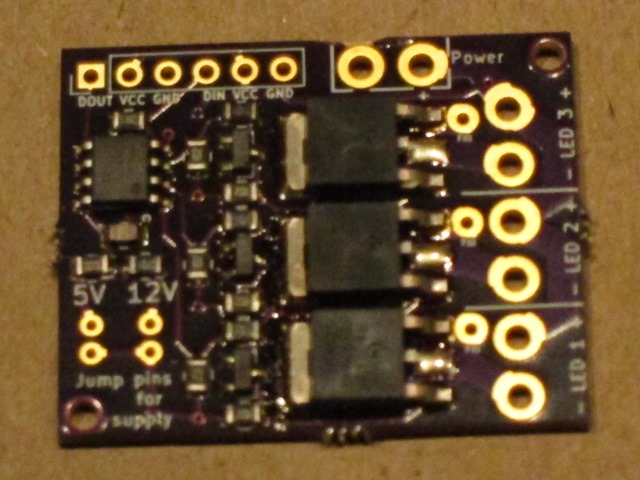
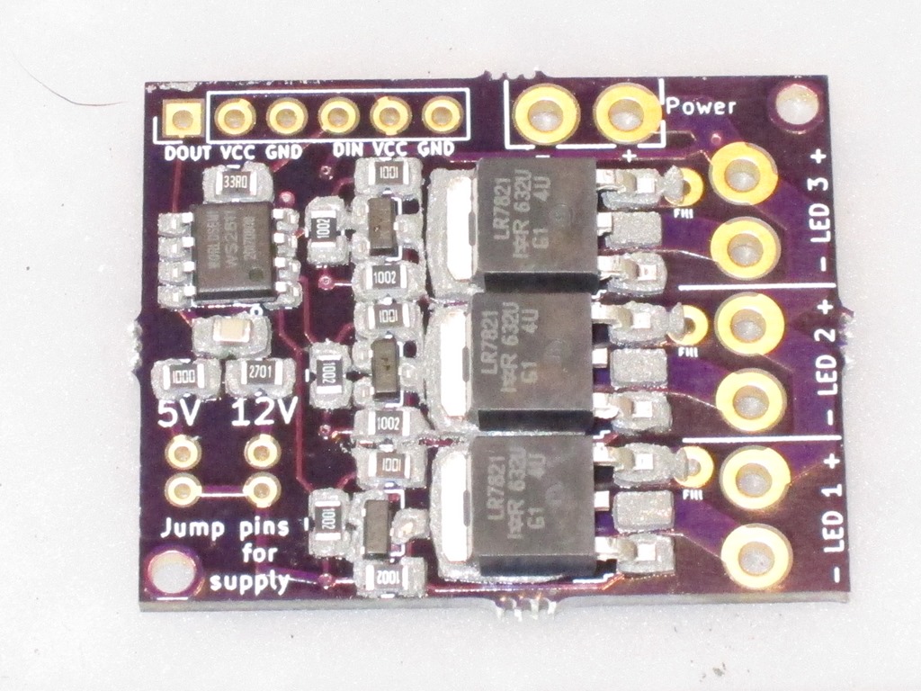
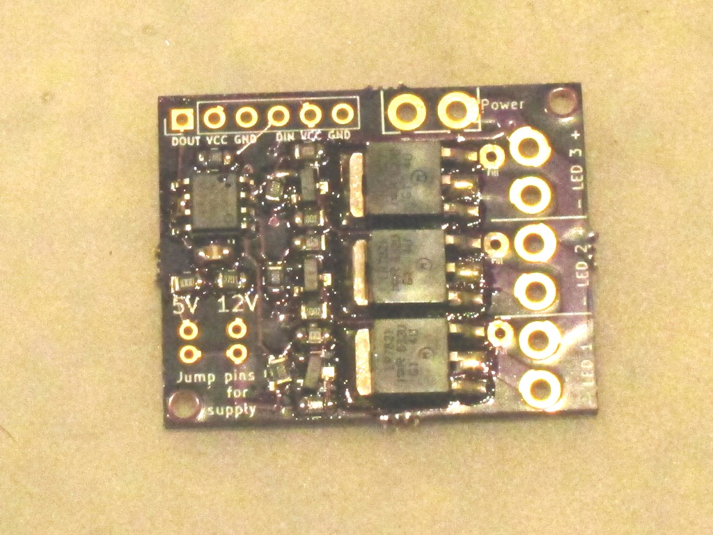
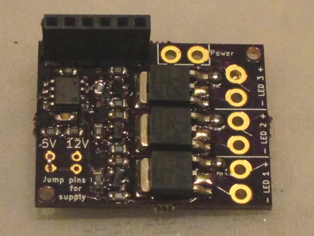
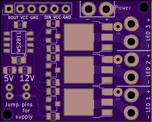
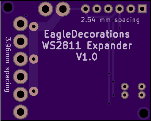
WS2811 Expander Part 6: of MOSFETS and voltage drops…

After I wrote the stress test article, I decided to put a voltmeter across the drain and source of the MOSFET and figure out what the voltage drop was. I hooked up the output to an LED ornament, watched the brightness cycle up and down, and put my probes on the MOSFET.

What I expected was pretty simple. In the sweet spot of the MOSFET I’m using, it claims a Rds – resistance between drain and source – of 10 milliohms. That means I should expect a voltage drop at 5 amperes of:

V = 0.01 * 5 = 0.05 volts

That low voltage drop is one of the reasons to use a power MOSFET; a bipolar transistor would have a voltage drop of about 0.6 volts, and therefore waste more power and get hotter.

The voltage jumped around a little, and settled down at full brightness:

0.8 volts

Okay, that is really unexpected; I played around with different voltages, and I still got 0.8 or 0.9 volts.

My first thought was that the MOSFETs that I got from Ebay might be counterfeit, so I waited for my order of real parts to show up from Arrow, built a new board, and it read:

0.85 volts

This is really confusing, so I asked a question on Reddit’s /r/AskElectronics subreddit.

The first answer I got was that it might be the base diode because I had the MOSFET backwards.

So, I pulled out the datasheet for the MOSFETS and looked at my schematic and board in Kicad. As far as I can tell, everything is wired correctly.

A deeper answer suggested that if I was doing PWM (I had been testing at brightness = 250 because I knew that would be more stressful for the MOSFET than always on), I should test with always on. It also talked about gate capacitance.

<digression>

This is one of those cases where real devices diverge from ideal devices. FET stands for “Field Effect Transistor” – current through the source and drain is controlled by the field on the gate. You establish a field by the flow of current to charge it up to an appropriate voltage.  The amount of current it takes depends on the gate capacitance (described as “Input Capacitance” on the datasheet). For the MOSFET to turn on, you need to flow enough current to establish whatever voltage you want on the gate.

Or, if you think of the gate as a capacitor, it takes a bit of time for it to charge. In my case, the time it takes to charge will be controlled by the pull-up resistance and the capacitance.

Let’s say we are running at 5V, and our MOSFET has 1nF input capacitance (pretty close), and we are charging through a 10K capacitor.

This calculator says that the time constant is 0.00001 seconds, or 10 microseconds.

</digression>

So, I went and changed the animation code to run all the way to full on – luckily my code is running on an ESP8266 and animations can be changed over WiFi – and rechecked the voltage drop.

Would it surprise you if I told you it was 0.8 volts? Probably not at this point…

Perhaps it’s my voltmeter; I have a nice Fluke but how about if I try using my oscilloscope (a Rigol DS1102D I picked up a while back)?

So, I powered it up, hooked it up, and looked at the waveform across the load. I showed the a nice PWM waveform…

But wait a second… I had updated the animation.

My debugging rule is that when things seem unexpected, back out a level and retest the assumptions. Usually one of those is wrong.

I started with my controller code. I suspected the gamma mapping code, so I added some Serial.println() statements and verified that, yes indeed, the colors were getting set to 255. So, that part was fine.

I next suspected the support library I use (the rather excellent NeoPixelBus). I read through a bunch of source but didn’t seem to be any issues. The code all looks fine…

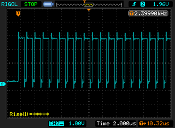
Was the data getting to the WS2811 correctly? So, I fired up the scope again and hooked it to the data line. On full on, the data looks like this:

NewFile0

The WS2811 uses an encoding scheme where a short positive pulse means “0” and a long positive pulse means “1”.

That is a full string of ones; you can’t see all 24 of them, but trust me when I say they are there. You can see this switch back all the way to all zeros as the animation progresses.

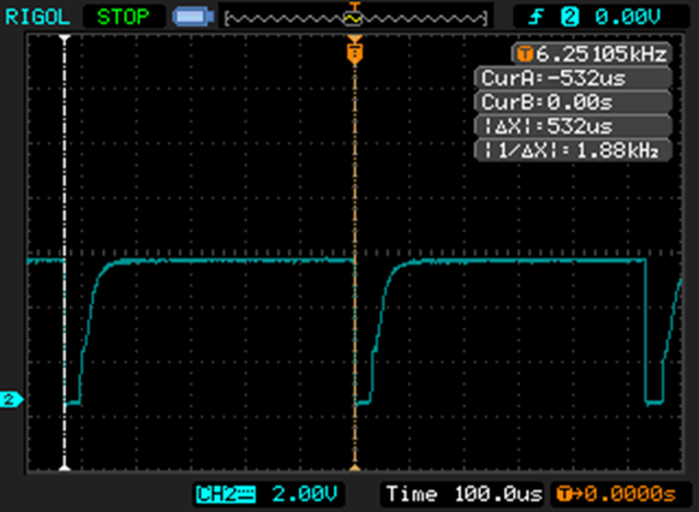
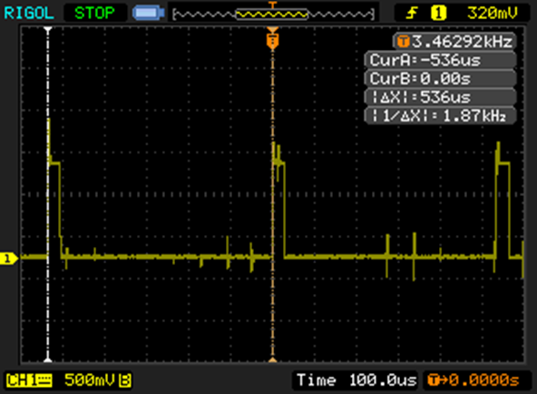
So, the software is telling the WS2811 to go to full bright, but it is still turning off for part of the cycle. Here’s the output straight from the WS2811:

NewFile4

That little positive spike is 29.4 microseconds, which is about 5% of the 536 microsecond cycle time, so full bright is only 95% bright.

The cursors on the capture show the start of two sequential PWM cycles, and the scope nicely tells me that it’s updating at 1.87 KHz. Which is another weirdity, since every source I’ve seen suggests that WS2811s update at 400Hz.

At this point I’m beginning to wonder if I have a WS2811 clone. I thought it might be the same IC used in the SK6812 ICs, but the claim is that they have a PWM frequency of 1.1KHz which is less than I am seeing.

So, it’s off in search of some real WS2811s. It is really easy to buy cheap ICs made in China but is surprisingly hard to find an authorized source. There are lots of sources on aliexpress, some looking pretty shady. Octopart found me a 10-pack from Adafruit for $4.95. I finally found lcsc.com, which specializes in this sort of thing, and ordered some. They look to be WS2811S chips, but I can’t find any information on what the “S” means. More on that when they show up.

Back to voltage drop…

Since the WS2811 wouldn’t go into “full on” mode, I needed a test setup to do my testing. Here’s what I came up with:

image

In the right middle is the MOSFET, with clips connected to the lead and the body. In the picture, it is running only the LED Star, which pulls 145mA of current.

One of the fun things about MOSFETS is the gate holds onto the charge, so if you just touch the gate to 12v, it turns on and stays on. Touch it to ground, and it turns off, and stays off. I measured the voltage drop across the MOSFET.

I next decided to hook up my test load. I started with a single 50 watt bulb, a 4 amp load. I carefully hooked it up in parallel with the led star, and…

There was a loud “crack” and the led star went out. No magic smoke, but the MOSFET was toast. The gate was floating, and there wasn’t enough charge there to put it firmly into full conduction, so it was in the linear zone and quickly overheated, melting the plastic on one of my clamps. So… replace the MOSFET, make sure the gate is attached to positive, and try again. That worked, and the MOSFET was only mildly warm. Let’s try two bulbs for an 8 amp load. That worked, *but* there is no heatsink and it got hot pretty fast, so I unplugged it before it got too hot.

I collected some data and figured out that the Rds was about 90 milliohms, which is a lot higher than the 10 milliohms I expected. That was a mystery for about 8 hours, until I was writing this up and realized that I was measuring the voltage drop at the ends of the leads connected to the MOSFET. The thin leads.

So, I went back and measured right at the MOSFET, and got a Rds of 7 milliohms, a bit better than the 10 milliohms that was spec’d. So, yay!

Faster switching

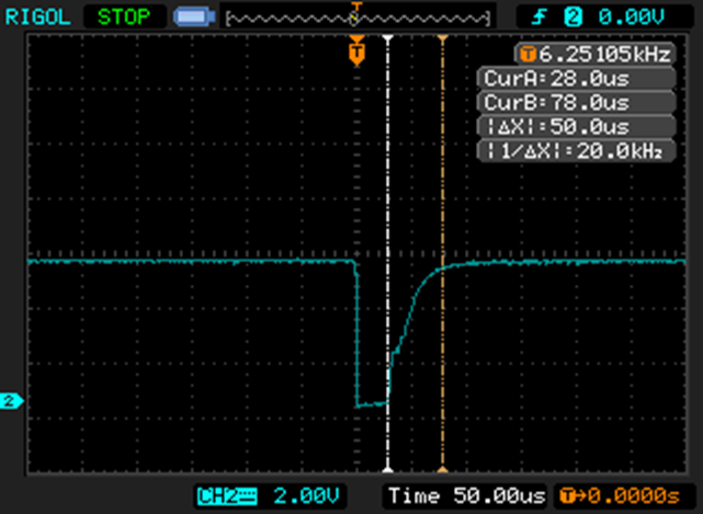
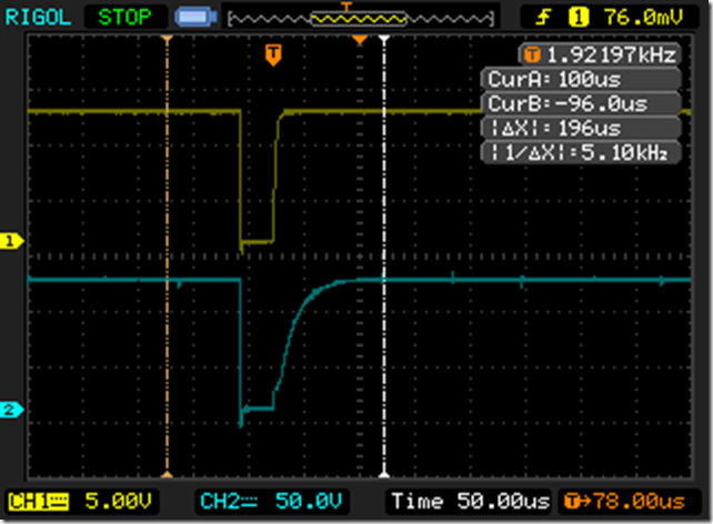
Returning to our somewhat slow switching, here is what I saw:

NewFile2NewFile3

The negative transition is when the transistor turns on; notice how effortlessly and quickly it pulls the gate voltage down. And when the transistor turns off, note how long it takes it for the gate voltage to charge back up. It’s roughly 10% of the overall cycle time.

Which is a bit embarrassing; I chose the 10K value as a typical pullup value, not thinking about the fact that this was happening on every PWM cycle. It can only supply about 1 mA of current.

The most obvious thing to try is to replacing it with a 1K resistor. That will result in 10mA of current and should switch roughly 10 times faster. Can the transistor handle it? The datasheet says that the 2N3904 can handle up to 200 mA continuous, so that will be fine. Is the base resistor okay? Well, transistor has a DC current gain of at least 50, so that means we need a base current of 10mA / 50, or 0.2mA. The 5V from the WS2811 will push about 4 MA through the 1K base resistor, so that’s way more than enough. It would probably be fine with a 10K base resistor, actually.

I took one of the boards and replaced one of the 10K resistors with a 1K resistor and then looked at the gate drive:

NewFile5

In case it’s not obvious, the top version is with the 1K resistor and the bottom one is with the 10K resistor. More than good enough for my application.

You meet the nicest people on the Zoo

Yes, “on the Zoo” is a strange wording; the reason for it might become apparent.

This afternoon I went on a bike ride. I go on a lot of bike rides; most of them don’t really warrant mention (got on the bike, rode, went home). This one might have showed up on Facebook as I sometimes do, so that my riding friends can “like” the ride as an indication of their recognition of my awesome cycling prowess (not really), and the rest of my facebook friends can… well, I’m not really sure what they think of those kind of rides, though “what a nutjob” is probably a good start…

You can look at the – which I cleverly named “A Grand Squaky Zoo” after the three hills I climbed (Grand Ridge, Squak Mountain, Zoo hill) – here. 38 miles, 4186’ of up, which is a lot for me in April.

But I digress…

The climb up Squak was a bit more painful than I had hoped, and I planned on skipping the Zoo hill climb, but I had to ride by it on the way home and turned up the hill on the spur of a moment. And immediately thought I’d made a mistake, as the bottom part up to the Zoo is steep. I came around the first turn, and noted a rider up ahead of me.

That’s a good thing; riders up in front of you are rabbits and you can focus on getting closer to them.

As I drew closer, I looked at his bike, because a bike can tell you a lot. Steel frame, fenders, pretty wide tires, and a handlebar bag in the front. That’s a touring setup. But many touring cyclists don’t ride hills, which meant it was most likely a Randonneur. Randonneur is a long-distance cycling discipline with events that are pass/fail based on elapsed time, so a 200 kilometer event (120 miles, or nearly 1000 furlongs) must be completed in 13.5 hours. Which isn’t really that out-of-the-ordinary, except that 200 km is the entry-level distance and the routes tend to be more than a bit hilly.

Where it gets to be a bit nuts is rides of 300, 400, or even 600 km; the local Seattle International Randonneurs 600k route involves nearly 22,000’ of climbing, is 383 miles long, and as a 600k has a time limit of 40 hours. There are also 1200k rides with a time limit of 90 hours; in that time you will climb 38,000’.

I like hills, but that seems a bit excessive…

As I pulled up next to the rider – why am I quite a bit faster than a randonneur rider? – I slow down to talk to him. Any distraction is welcome on a long climb, and this one is going to take me 36 minutes today – so we start talking, and he mentions that this is a training ride for him; he rode over from Freemont and he’s going to ride up this climb 6 times and then go home.

6 times. Well, if I was going to ride it 6 times (for about 7000’ of up total), I guess I’d be riding it fairly slowly as well.

Turns out his name is Doug Migden, and he’s training for the Transcontinental Race, a self-supported race across Europe. In 2015, he rode the 4200 km and climbed 35,000 *meters* in 446.5 hours. There’s a great writeup of his experience here.

I often wondered what you do if a 1200k ride isn’t long enough, and now I know. It’s always nice to run into people that are crazier than you as it lets you feel that you are sane.

We chatted and I learned a lot about long-distance self-supported riders. As we got about 3/4 of the way, I turned left to head to the classic top of the climb. Normally I don’t think you have done the Zoo if you don’t do the top, but a) Doug was going to an alternate top, and b) he was doing it 6 times, so I think I’m going to cut him a little slack.

And damn, was that descent cold.


WS2811 expander part 5: 12V stress test…

One of the points of the expander is to be able to drive bigger loads than the 18mA that the WS2811 gives you directly. Much bigger loads.

To do that, I needed something that would stress the system, and I needed to verify that the design worked with 12V.

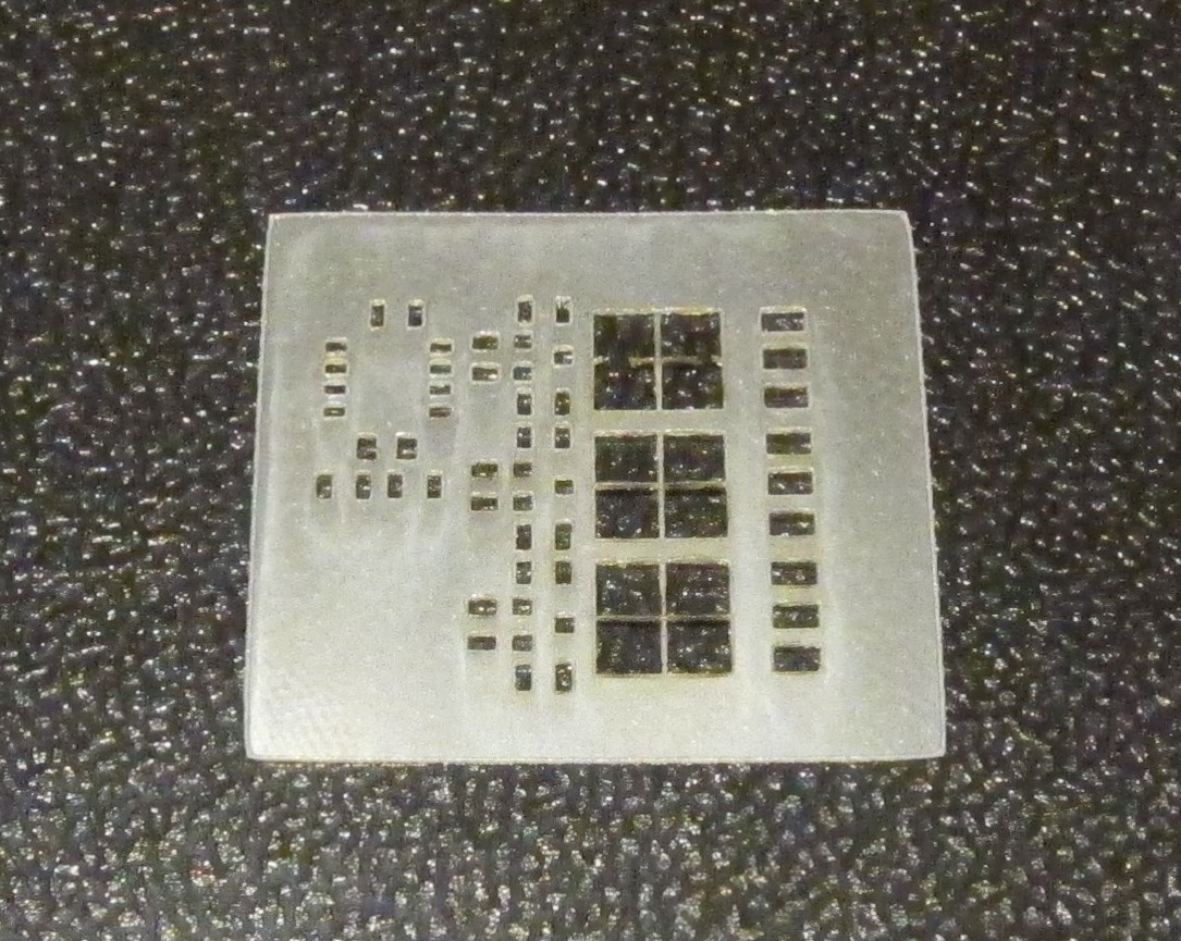
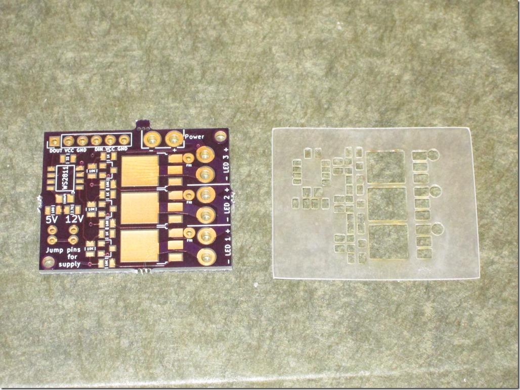
First off, I needed to cut a new stencil uses the paste layer:

IMG_9501

That’s a bit nicer than the first one; there is adequate spacing between the pads this time.

Aligned it on the board, applied paste & components, and reflowed it. Here’s the result, still warm from the oven:

IMG_9502

All the components self-aligned nicely, no bridges, no missing wires. Perfect.

The only thing I need to do is get rid of the center pad for the MOSFETs, since they don’t actually have a center pin.

How to test it?

Well, I dug through my boxes and found a 5 meter length of 12V LED strip. It says that will be 25 watts. I hooked it up and verified that all 3 output channels are working. It’s running an animation that ramps from 0 to 255 over 2 seconds, holds for 2 seconds, and ramps down for 2 seconds. I chose that because the quick switching is the hardest for the MOSFET to deal with from a heat perspective.

But 2 amps isn’t quite enough. I dug out a 12V power supply that claims it can do 6 amps and hooked it up to one output channel:

IMG_9504

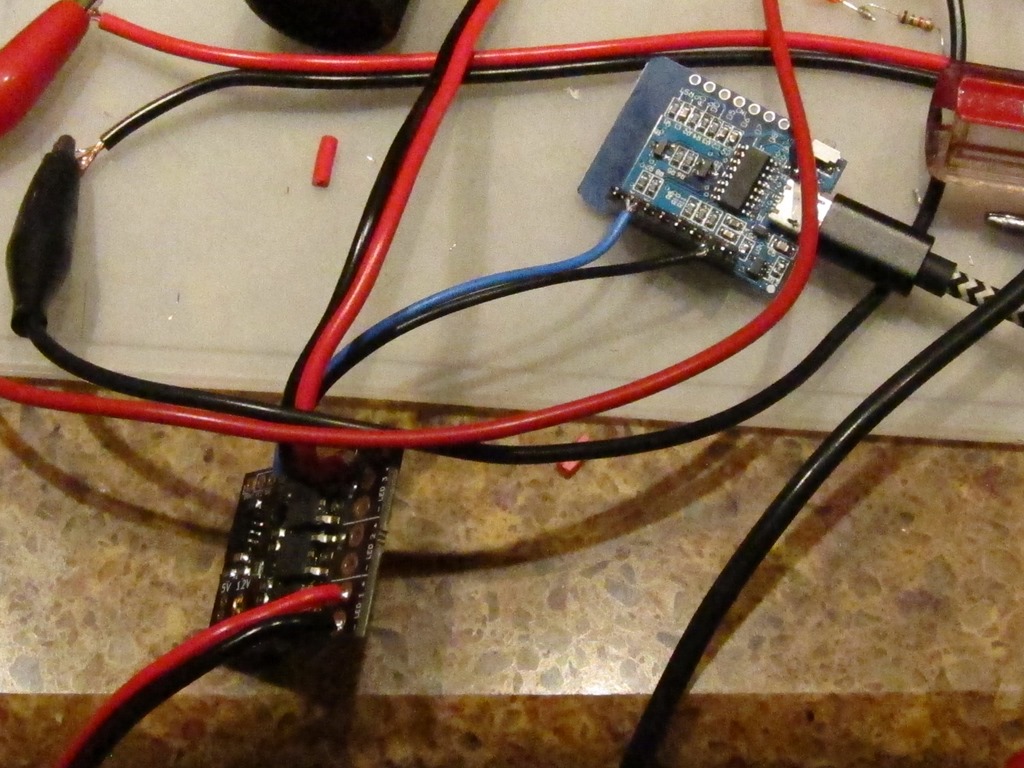
That’s the NodeMCU board in the upper right, powered by LED, the data and ground running to the board, and then some decently-hefty wires running to the board.

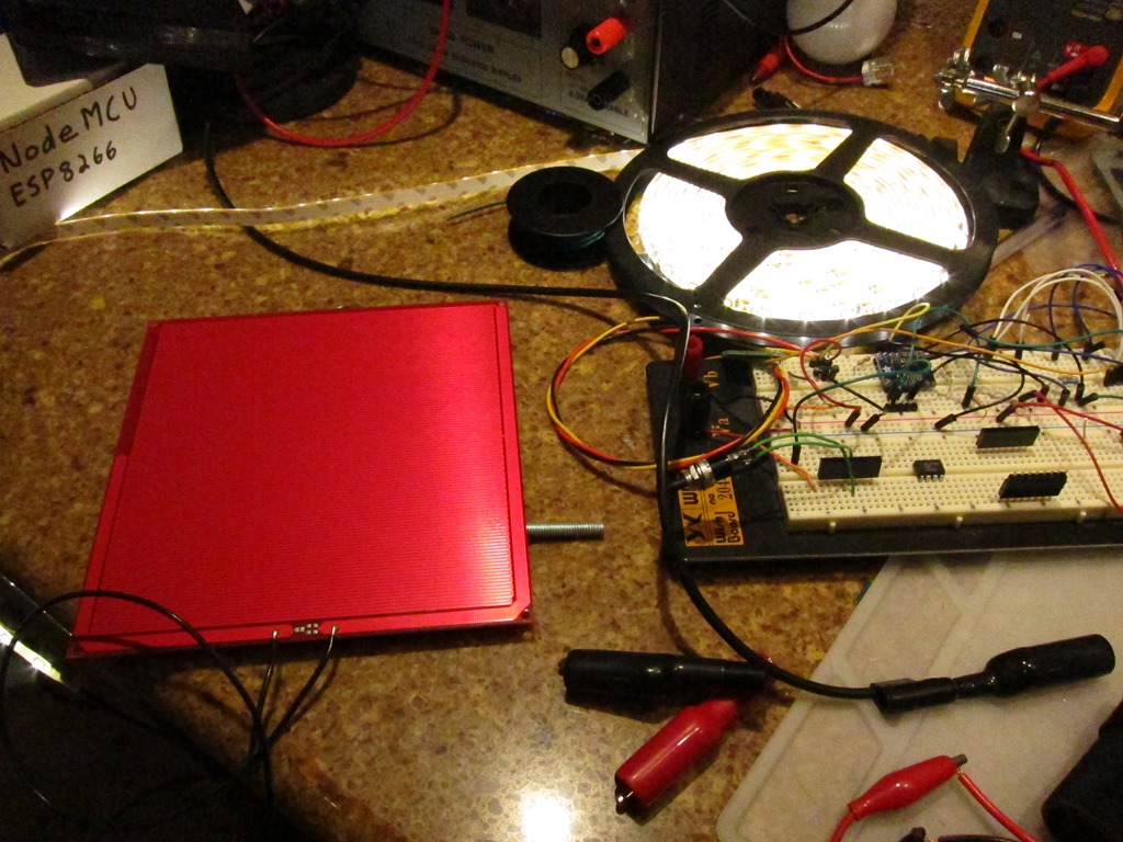
More load, more load, more load. I want something that soaks up the 12V. Incandescent car bulbs are nice but I don’t have any handy. But I do have an extra heated bed for my 3d printer; it’s a nice 6” x 6” pc board. Hooked that up in parallel with the lights:

IMG_9505

Ignore the breadboard…

This worked just fine. The board heated up to about 170 degrees, the lights worked fine, and the MOSFET on the driving board just *barely* heats up. My measurements show that it’s switching about 5 amps of current.

The only one that’s not happy is my cheap power supply, which is putting out a nice 10Khz (ish) whine when under load.

I switched over to run it on all the time to see how that affected things. After 10 minutes, the board is up to about 110 degrees, the printer bed is up to 240 degrees, and the 12V power supply is 125 degrees.

I think I’m going to rate it at 6 amps total; that gives a lot of margin, and frankly 70 watts is quite a lot of power for this application.


WS2811 expander part 4: Boards and Parts!

After a bit of waiting, the boards showed up from OSHPark. they looked fine as far as I could tell.

I had all the other parts to do a board, but I needed a paste stencil. I went into pcbnew, chose File->Export, and then chose to export the F.Mask (ie solder mask) layer to a SVG. I cleaned it up a bit to remove non-pad elements, went out to the laser cutter and cut a stencil out of 4 mil mylar:

IMG_9495

Everything looked pretty good; there was good alignment between the board and the stencil. The spacing between the pads looked a little tight, but it’s a fairly fine pitched board, so it was mostly what I expected.

I carefully aligned the stencil and taped it on, got the solder paste out of the fridge, and applied it. Pulled up the stencil and it looked crappy, scraped it off, did it again, and got something that looked serviceable though there was more paste than I expected. Hmm.

Got out the components:

  • 1 WS2811
  • 1 33 ohm resistor
  • 1 2.7k ohm resistor
  • 6 10k ohm resistors
  • 3 1k ohm resistors
  • 3 NPN transistors
  • 3 MOSFETS
  • 1 100nF capacitor

and it took about 5 minutes to do the placement. Here’s the result:

IMG_9496

I didn’t look at the picture at the time, but that’s a *lot* of solder paste.

Into my reflow oven (Controleo 3 driving a B&D toaster oven), let it cycle, seemed fine, here’s the board:

IMG_9499

Not my best work. Frankly, it’s a mess; there are obvious places where there is no solder, and obvious pins that are bridged together. I spent about 15 minutes with my VOM testing for continuity and there were 3 solder bridges and 7 unconnected section.

Something clearly went wrong. And I went back to PCBNew and it was *really* obvious.

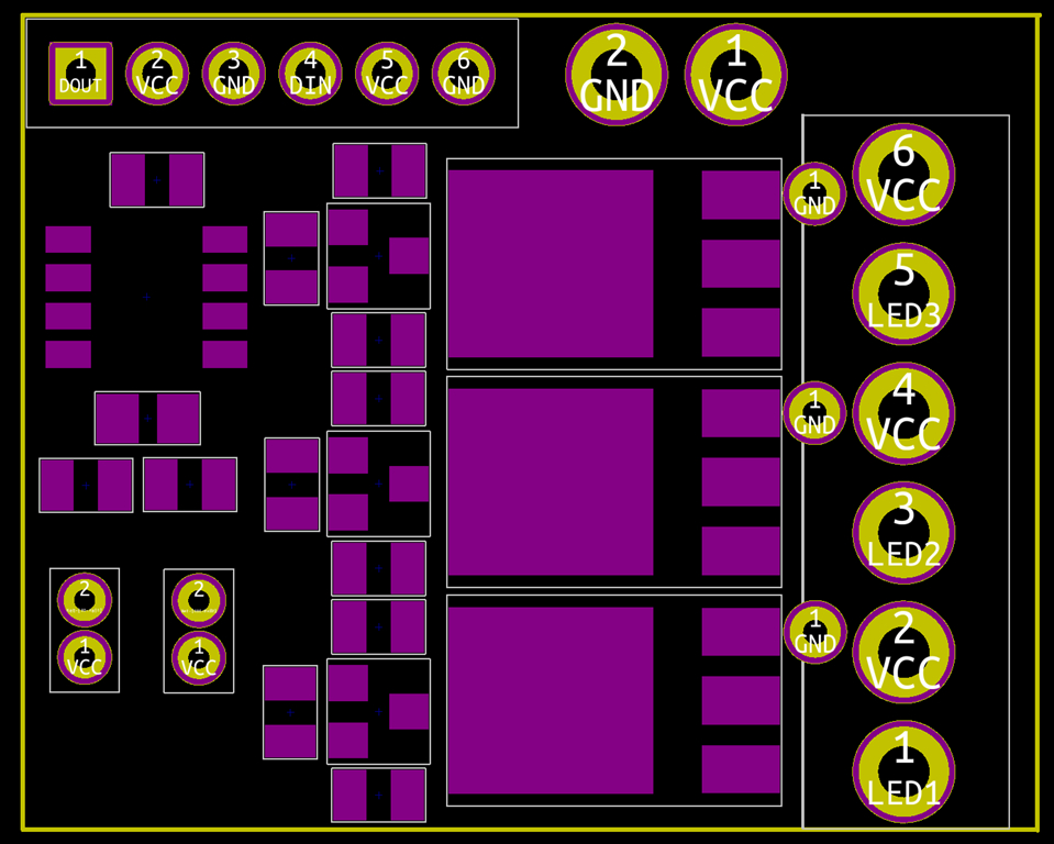
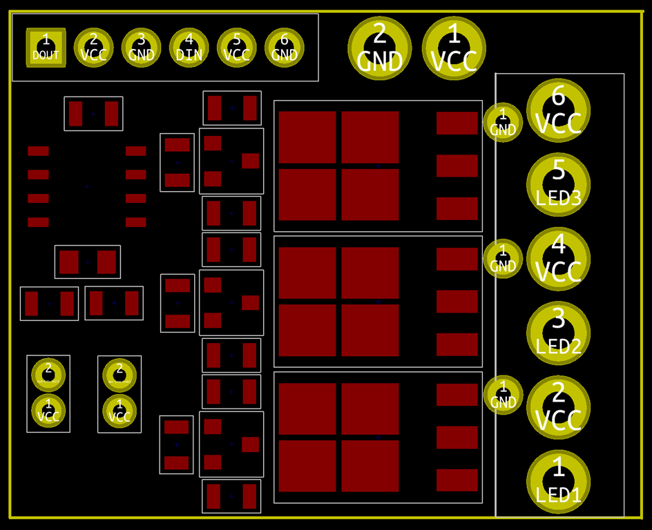
The layer you should choose for your stencil is F.Paste, not F.Mask. Here are the two next to each other (Mask left, Paste right):

imageimage

The Mask layer sizes are positively giant compared to the paste ones. So, what happens if you use the Mask layer is that you have:

  • A *lot* more paste on the board, especially the small pads which must have double the amount
  • Solder paste with much reduced clearances.

What that means in reality is that when you put the components on, it squishes the solder paste together and connects pads that shouldn’t be connect. And then when you head it up, you either get bridges or one of the pads wins and sucks all the paste away from the other pad (how it wins isn’t clear, but it is clear that the huge MOSFET pads pulled all of the paste from the transistors next door).

This makes me feel stupid, but it is actually quite good news; it means that the design is fine and I just need to remake a stencil with the correct layer.

Anyway, after a lot more rework than I had expected, I ended up with this:

IMG_9500

It’s still an ugly board, but does it work?

Well, I hooked up 5V, GND, and data in to one of my test rigs and a LED to the LED outputs.

And it works; the LED is on when I expect it to be on and off when I expect it to be off. All three outputs are fine.

The next test will be some testing to see how it fares with switching high current. And I’ll probably want to make another one using the correct stencil and hook it up for 12V operation to verify that.


New kit: LED Candy Cane part 1

My first kit – the Dodecahedral Light Engine – has been selling about as well as I expected a very hard to construct project with limited usages to sell, which is not very well. I primarily did it because I was going to do them anyway for my decoration project and wanted a project I could learn on.

I’ve just started working on my second kit, which is going to be a lot easier to build, cheaper, and more widely useful.

One of my favorite displays is a “tree of lights”, which is a tree with custom LED ornaments on it:

The ornaments are made of small sheets of plexiglass with high-power LEDs inserted into the holes, wired up, and waterproofed.

They are really bright; note in the photo that all of the dim lights are normal brightness LEDs, and even at that level the ornaments overpower the camera sensor. They are bright enough that – and I am not making this up – they cast a shadow about 50 feet away when they were at full brightness, so I dialed them back a little in brightness.

These ones are driven directly from 120VAC as that is what the controller provides.

What I want from this project.

  1. A fun, easy-to-assembly ornament
  2. The ability to run off of 5V or 12V (*maybe* 120VAC with a big disclaimer that you shouldn’t really do it)
  3. Tunable brightness
  4. The ability to drive them as WS2811 nodes (see my WS2811 expander posts…)
  5. A frame/armature that is easy to produce automatically (the originals were done with a 5mm end mill in a drill press and took a *long* time).


How do I become a better skier? Stance and Turn Shape

I’ve been seeing a common question recently – how do I become a better skier? – and I’m immodest enough to think that I have something useful to say on that topic. This is a summary of how I approach skier improvement for adults when I’m teaching.

I guess I should start by defining exactly what I mean by better. It’s one or more of the following:

  • Able to ski a wider variety of terrain
  • Able to ski a wider variety of conditions
  • Able to ski more efficiently – with less effort and/or for a longer period.

Prerequisites

There are a couple of prerequisites that are required for you to learn efficiently, which I call “happy and casual”…

Your happy place

Skiing is inherently a physical skill, and I can’t physically make your body parts move the way that I want to see them move. The best that I can do is try to provide you with opportunities through which you can discover better ways of moving.

To improve the chances of that happening, you need to be able to pay attention to what is going on, process what is going on rationally, and be able to explore modifications to your current technique.

For that to work well, you need to be calm and focused, which I just label as “happy”.

For us to reach that state, we need to feel safe, and it helps a lot of we are also having fun. If you feel scared or distracted, it is very hard to make progress.

Spending a lot of time skiing slopes that are too hard for you is a great way to be in a mental state where it’s hard to improve, and it’s also a great way to develop bad habits.

However, having said all that, you don’t learn to ski bumps on the bunny hill. Part of learning to ski off piste is getting used to skiing off piste so that you can be in that situation and stay in your happy place, or at least not in your very sad place. A little challenge is good as long as you track your mental state and are functioning well in it.

Your casual place

Compare two scenarios. In the first, you are doing a turn every 5 seconds. In the second, you are doing a turn every second.

Which one is easier to analyze and pay attention to?

The first one is obviously much much easier to analyze.

Part of this is terrain choice – choosing a terrain where, at our current ability, we can make turns that are what I would label as “casual”. They’re easy, I don’t have to work very hard, and most importantly, I’m not scared that I’m going to fall.

The second part is about technique; finding ways to modify your technique so that a given terrain becomes more casual for you.

Note that “casual” is about how you feel in a specific situation. Some people are casual on easy intermediates. Some are casual on black diamond bump runs.

Foundations

There are two topics that come up all the time, often enough that I consider them to be foundational. And by foundational, I mean that not addressing issues will limit your ability to improve. Those two things are stance, and turn shape.

Stance

If you ask 10 ski instructors what the most common technique issue for skiers is, 9 out of 10 will say “leaning too far back/not leaning forward enough” (the tenth is daydreaming about skiing). And from that comes the common advice:

  • Lean more forward
  • Keep your hands up in front of you
  • Don’t look down.

Does that work? Well, it can work, but it often doesn’t work great.

It helps to go back to what instructors call “ski/snow interaction”. What are we trying to achieve with ski/snow interaction? WRT stance, it’s two things:

  • We want to be able to load (put pressure on) the skis so they will bend and we can therefore use the sidecut to do the turning for us.
  • We want to have our weight centered over the skis so that we are going down the slope at the same rate the skis are, so they are not trying to speed up and get away from us.

That boils down to “have enough weight/pressure on the front of the ski so that I can get it to bend and keep up with it”. And the way we exert pressure on the front of the ski is only though the shin pressing on the front of the boot.

Which means there is one bit of anatomy that matters more than the rest: the ankle. If the ankle is flexed and there is pressure on the front of the boot, there is pressure on the front of the ski. If it is not flexed, it doesn’t matter how you are leaning or where your hands are, there isn’t pressure on the front of the boot, there won’t be pressure on the ski.

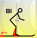
Here’s an example of  the kind of stance that I commonly see:

image

Note how the ankle is loose, but also note that the skier is a) leaning forward and b) has hands in front. Those “lean forward, hands up” cue is not working for this skier.

I want that ankle joint to be tighter, something that looks like this:

image

The ankle joint is tighter – the shin leans forward – but note that the skier is leaning forward less and has hands that are closer to the body.

Looking at the joints in the two images, where are there big changes? The knees have moved forward quite a bit, but the biggest change is in the hips; they have moved forward immensely in the second image. Which leads to my first cue to correct stance; stand up taller and move your hips forward. And also try to keep the angle of your back the same as the angle of your shins.

Not only is this a more functional stance, it’s also a more comfortable stance as it relies more on your skeleton to hold your weight and less on your muscles. Great stuff all around.

That is the stance that I’m searching for.

However, there is something problematic here. Let’s say you are skiing something that is challenging for you to ski and you find yourself in the first position. To get to the preferred, you need to stand up, get your hips forward, and do this while your skis are trying to run away from you. That is generally hard to do because it’s a lot of mass to move, so “stand up and move your hips forward” doesn’t work so great in a dynamic situation.
What is the minimal thing we could do from the first position to get pressure back on the front of the skis? What would be the quickest move? Focus on the ankle…

image

If we can pull our feet back 5 inches, we can regain the pressure on the front of our skis and get them working properly again, and we can make that move much faster than trying to move our whole body forward. It’s not a perfect stance; it’s still too hunched and is going to burn out your legs faster, but it goes us back to a place where they skis are actually working.

I think that move is foundational in off piste and bumps.

Finding the right stance

Remember the part earlier where I said that my job is to put you in situations where you can discover a better way of moving? The following is what I recommend to so you can discover what the right stance feels like and ingrain it into your neuromuscular connections. It has four steps.

Step 1: Sideslip

In a sideslip, we start with our skis across the hill and roughly equal pressure on both of the skis, and then roll our ankles and knees down the hill until our edges release and we start to slide downhill. Try it facing both directions, and roll your ankles and knees back into the hill to stop.

Here’s a video of what it looks like.

You don’t have to be perfect at sideslip for the purposes of this, but if you have trouble with steps 2 or 3 come back and practice this more.

Step 2: Falling leaf

Start in a sideslip where you are moving straight down the mountain, and slowly shift your weight forward and back on your skis. When you have the weight forward, your sideslip will move sideways down the hill and go forward at the same time. When you have your weight backwards, your skis will go sideways and backwards at the the same time.

Here’s a video of what it looks like. Start by doing it more slowly than the video shows. Pay attention to what your legs and ankles feel like as you are going forward.

Step 3: Diagonal forward sideslip

This is the forward part of the falling leaf held for much longer. Start by going across the hill, and then roll your ankles and knees down the hill slightly to sideslip at the same time. You will need to be in the “forward falling leaf” position for this to work, with ankles flexed and pressure on the front of your boot, and it will feel weird when you first do this. Play around with your stance. Try to stand tall.

It looks like this.

The feeling you get in the forward part of the falling leaf and in the diagonal forward sideslip is the foundation position you want in your stance.

Step 4: Diagonal forward sideslip with turn

Take the diagonal forward sideslip, and add a turn at the end of it. Make sure you are in the sideslip as you start the turn, and then as you exit the turn, get back into the diagonal sideslip. You should find your turns to be much easier.


Turn Shape

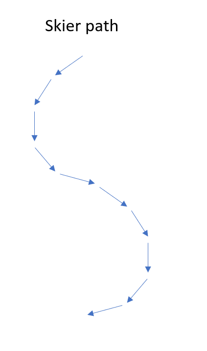
We talk about this foundation as “turn shape”, but I think that is probably the wrong way of looking at it. What we really care about is not the shape of the turn, but the direction that your skis are pointing during the turn compared to the direction that your body is moving. Perhaps a few diagrams will help. Let’s say you are skiing the following path:

image

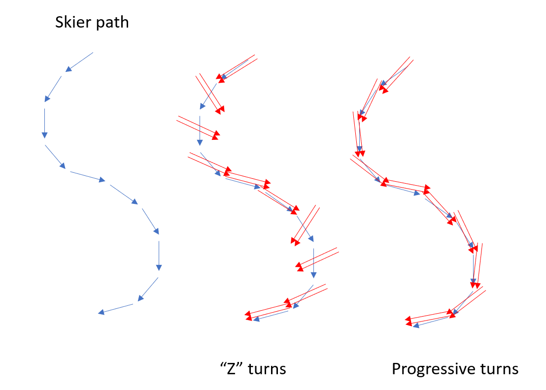
That looks like a nice smooth turning shape. Let’s overlay the direction the skis are pointing in two different turning techniques:

image

In what we call “Z” turns, at the beginning of the turn, the skis are pivoted quickly across the path of travel and then held relatively straight until the next turn, where they are pivoted quickly across to the other direction. Z turns are problematic because:
  • They require big movements and therefore a lot of energy
  • Because the turning is quick, they ask more from the condition of the snow; if the snow is scraped off or a icy, they feel much more precarious.
  • The motion is so fast that you can’t actually feel what they skis are doing. Remember my part earlier about turns feeling casual so you can focus on what your skis are doing? Z turns make it hard to do that.

In progressive turns, things happen *slowly*, so you can easily tell what is going on.

So, if progressive turns are so much better, why do so many people do Z turns? It’s very simple; if you try to do progressive turns with a rearward stance, your skis take off downhill when they are pointed at the fall line, and you fall over.

My experience is that you can fix your stance, it’s generally fairly straightforward to move towards more progressive turns, but if you want an exercise, I think shuffle turns work pretty well. They are also good because you can’t do them if your stance is too far back.


WS2811 expander part 3: PCB Revisions again…

More revisions.

I posted the design to /r/PrintedCircuitBoard, and of the comments said:

“Do you need pullups on the outputs of WS2811?”

And of course, I was confident the answer was “no”. For about 5 seconds. And then I measured the WS2811 I have in my breadboard; it gave a nice solid sink when it was on, and when it was off, just a fraction of a volt. Clearly not up to sourcing current to the NPN transistor.

The most likely explanation is that it’s an open collector output:

The collector on the output transistor is just left hanging – it’s only collected to the external pin. The voltage on an open collector can float up above the internal voltage of the IC as long as you don’t exceed the maximum voltage of the transistor

Open collectors are really useful if you want to have a bus architecture with multiple components able to pull the bus low, or if you aren’t sure what voltage of the output is going to be. Since the WS2811 can be used to drive LEDs tied to either 5V or 12V, it makes perfect sense. And it is confirmed by the internets.

Which means that the circuit needs to get a tiny bit more complicated:

image

Another pullup resistor is added to the mix. Really not a problem from the cost and assembly perspective as the design goes from 9 resistors to 12 resistors.

But, can I fit it in the current board layout without making it bigger?

I should probably add a parenthetical note here that says it’s often easier to go with a bigger layout, and in fact if you are going to hand solder a board, you *should* go with a bigger layout. Though I’m not sure how practical it is to solder the MOSFETS by hand since the base pad is so big…

Anyway, here’s what the board looked like before:

I need to put a resistor between each of the traces that head from the WS2811 over to the transistors. Hmm.

I initially just tried to fit them in there, and with a big of rerouting, I was able to make it fit. Technically.

Then I decided that it would be a lot easier if I moved the vertical ground trace underneath the transistors and used that to provide the ground connection to the transistors. That meant I could move the VCC vias around more easily, and could do the following:

image

The fit in reasonably well.

I *think* it’s ready to order the first version of the board, but there’s one more step. I now have on hand the WS2811 ICs and both kinds of transistors. So, I printed out a design with the copper layers shown, and did a test to see if the components really fit on the board.

image

That shows the WS2811 on the left, the MOSFET on the right, one of the NPN transistors and then a tiny 0805 10K resistor at the top. Everything looks like it will fit fine.

I ordered 3 boards for $7.10 from Oshpark, which is my usual supplier for prototype boards if they are small.


WS2811 expander part 2: PCB Revisions

I’ve done quite a few improvements on the board. Let’s look at before and after:

imageimage

My usual flow is to do some changes, and then load the board into OSHPark and see how it previews. And then make changes.

I’ve probably redone the majority of the traces on the board. The big changes are:

  1. I replaced the 0603 resistors with 0805. I’m going to do the components by hand, and the larger resistors are easier to place. And I have a set of 0805s sitting in my drawer.
  2. I realized that I hadn’t planned for chaining together more than one board. After 3 or four revisions, I settled on a single 1×6 header to hold both sections. You can either use two 1×3 headers or one 1×6.
  3. The big headers for power and the LED output were bigger but not a standard connector, since I just wanted them to be easier to solder to. That was stupid. They are now spaced to use standard 3.96 mm spacing (Molex KK line if you want branded stuff), so you can either solder or use a connector. This made the board just slightly taller.
  4. The transistors and resistors have been moved, aligned, spindled, and mutilated.
  5. Added holes for mounting, though it’s probably not needed with a board this small. But I had space.
  6. Added some more labels.

Updated schematic

image

Board shots

I’m thinking this is probably good enough to get my prototype versions built.


WS2811 expander

I’m starting a new decorations project that will involve a fair number of standard LEDs, but not addressable ones. I have a few different use scenarios:

  1. Plug into a standard USB power supply.
  2. Power directly with 120 VAC.
  3. Power either with 5V or 12V and have an easily way to control brightness…

The first two are just wiring, but the third needs something more. My target market is quite used to using WS2812 addressable LEDs, so I’m going to build something that works in that environment.

Quick requirements list:

  1. Runs on 5V or 12V.
  2. Uses WS2812 protocol.
  3. Can drive significant loads (at least 10 amps).
  4. Small and cheap

The second requirement is pretty simple; you can buy the WS2811, which works exactly the same way as the WS2812 lights but is in a separate package. And it very conveniently has a little internal power supply that can use 5V or 12V by changing the value of one resistor. Here’s a typical 5V circuit:

image

Looks very nice, and almost does what I want, except that it’s designed to only sink 18.5 mA, which is quite a bit less than my 10 amp goal. I don’t strictly have a use for 10 amps right now, but I will likely need at least 1 amp for some uses.

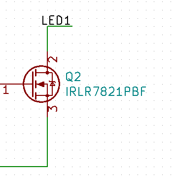
So, I’m going to lean on the IRLR7821PbF MOSFET that I used in my backyard controller, which it looks like I can get for about $0.14 each. It’s pretty easy to use:

image

I will just drive the gate of the MOSFET with the output of the WS2811, and when the MOSFET turns on, it will pull the LED1 line low, turning on the LED.

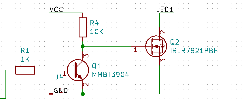
Except… the WS2811 outputs are active low, and the MOSFET in this arrangement is active high. So

image

We add an NPN transistor. If the input is low, the transistor is off and the gate on the MOSFET is pulled high by the 10K resistor. If the input is high, the transistor is on, the gate is pulled low, and the MOSFET is off.

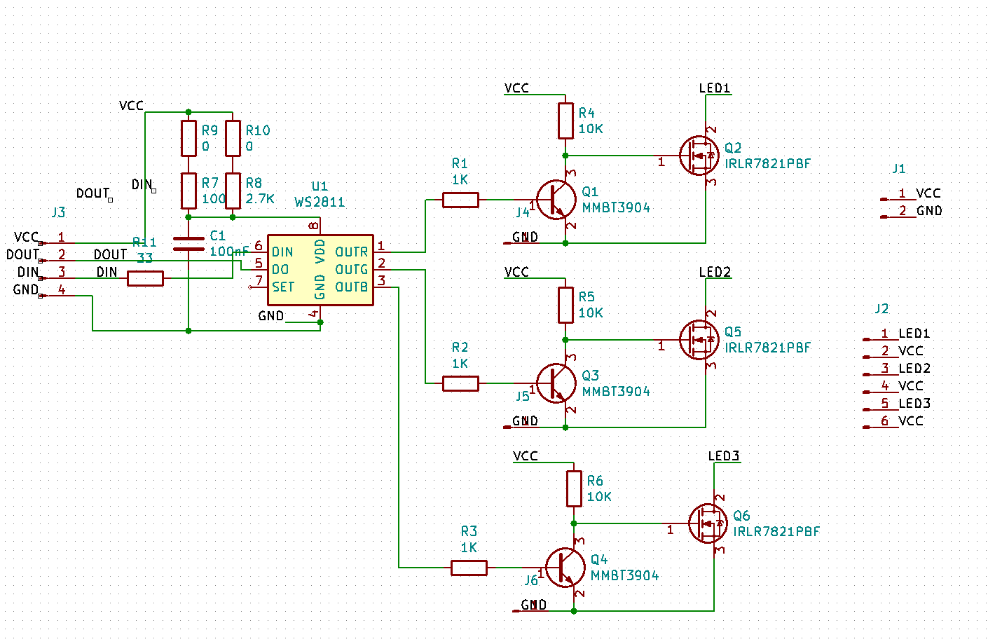
That will be duplicated for all three channels, and we end up with the following:

image

R9 and R10 are really just empty holes; you bridge R9 with wire if you want to use 5V and R10 if you want to use 12V.

I unfortunately generally forget to take snapshots during PCB design, so here’s the V1 state:

image

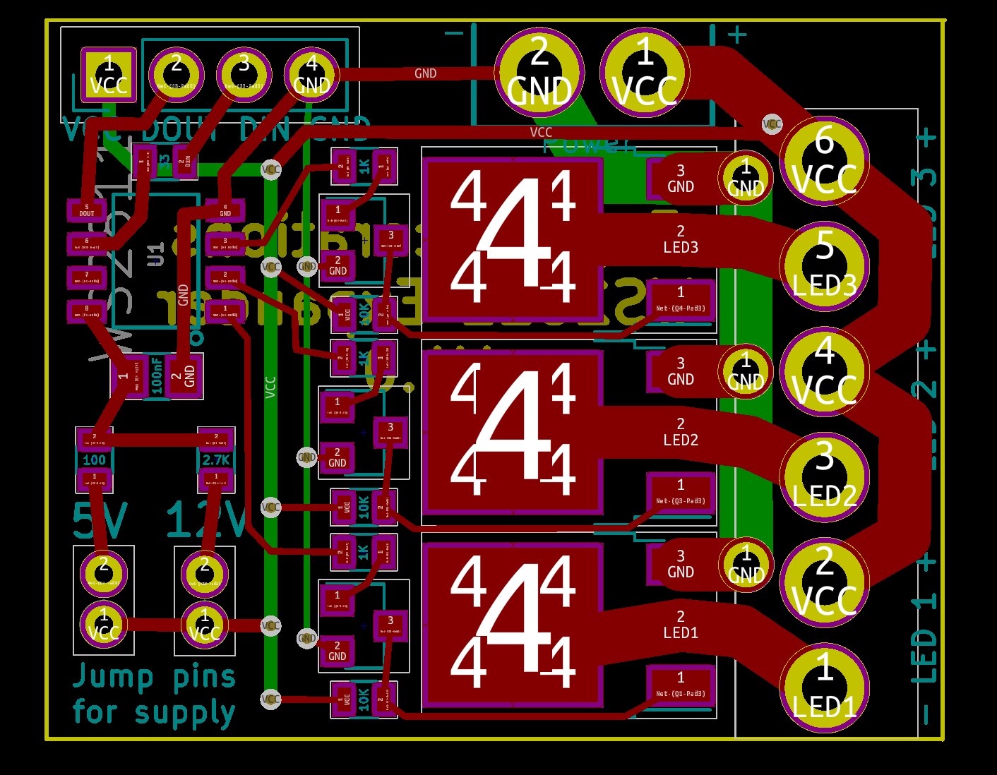
The MOSFETs have lots of 4s on them – I don’t know why – and to the left are the bipolar transistors and the resistors required for that part of the circuit.

The power input holes and the LED holes are designed to use Molex KK 396 headers and connectors so you can either use those or hand wire.

The lower left shows the jumper locations to set voltage.

All resistors are 0603 sized; that makes them compact but still relatively easy to populate.

The only weirdness are the three through-holes next to the LED terminals. I need to tie that backside ground trace to the frontside MOSFET terminal, but I was having trouble fitting enough vias to carry the current. Instead, I just used the through holes, which will be filled with solder and therefore be able to carry plenty of current.

The board is about 40mm x 28mm in size. I might jump up to 0805 resistors to make it a little easier to fabricate.

Before I send it off to be fabricated, I need to have the transistors in hand so I can verify the layout works.


The endurance athlete’s guide to fueling and weight loss part 6: Recommendations

This post will make considerably more sense if you have read the previous posts

After five long and sometimes tedious posts, I’m finally going to tell you exactly what your base diet should be and and how to fuel during exercise to achieve your goals.

Ha.

I sincerely wish I could do that, but the reality is that everybody is different (genetics, age, sex, metabolic condition) and we all have different goals (win that race/lose weight/have fun), so I’m not able to do that.

What I do think I can do is talk to you a bit about my philosophy of endurance eating and fueling and how you might apply it to your situation. And then I’m going to turn you loose to experiment/adapt/modify the recommendations to adapt them to your specific situation.

Philosophy

Based on the way our biochemistry works, here’s are the principles I advocate:

  • Train in ways to improve fat burning, and therefore improve the ability to use fat as a fuel so that more fat is burned and less glycogen is used, so there is less hunger.

  • Fuel in ways to support glycogen stores and therefore support endurance and performance without getting in the way of fat burning.

  • Eat in ways to support the first two goals and to leave us generally healthy.

The application of these principles is going to depend on your current weight, fitness state, goals, number of cats you own, etc. In the following sections I’m going to talk about some broad guidelines, but you will need to do experimentation and tuning yourself.

Train in ways to improve our fat burning

Doing training to specifically increase fat burning has been a thing for a long time; there was, for example, a big push towards LSD (either Long Steady Distance or Long Slow Distance) training in cycling in the early 2000s. And it worked okay, at least for some people.

But what it was missing was the dietary and fueling aspect; if you have a lot of glucose in your system during the training, you get improved endurance but you get little improved fat metabolism.

While thinking about this section, I remembered a mountain training ride I did with a couple of friends back in 2006 or so; it was scheduled for about 115 miles and around 8K of up. I was getting ready, stuffing my jersey pockets with little ziplocs of drink mix and other foods – probably 1500 calories worth – and I noticed one of my friends just standing there. I asked him what he was taking for food, and he pulled out a little bag of trail mix. He said, “I usually don’t eat much on rides, but I’ll have some of this if I get hungry”. Another paradox that the “you have to eat lots of carbs” model doesn’t explain.

The way that we improve our fat burning is exercise in situations where glucose is scarce. What does “scarce” mean in practice?

I don’t know.

Perhaps “scarcer” would be a better word to use, and in fact fits in better as I advocate an incremental approach. Take the amount of carbs that you eat before/during/after, and reduce it by some amount.

If you generally don’t eat on your workouts, pick one of your workouts – perhaps a longer weekend one – and do it fasted.

If you are a carbs before/during/after kind of athlete, look at the amount you are eating and cut them down. From a biochemical perspective, targeting the pre-workout carbs – so that you start with lower glycogen stores and steady blood glucose – is probably going to be more impactful, so maybe you cut down or eliminate that snack first. Or maybe you cut down all your carbs by 30%. And then go out and do your workout.

Generally speaking, longer steady workouts are much better for this than fast short ones. Use whatever definition of “long” that works for you.

Do that for a few weeks or even a month or two, evaluate how it’s working compared to your goals, and see if you want to make further changes.

Fuel in ways to support our glycogen stores

Didn’t I just tell you to reduce your carbs during training, and now I’m telling you to increase them?

Not quite.

While there are some athletes who eat full keto (very low carb) diets and use either no or very few carbs during workouts and races, there’s no prize for doing that nor is it a morally superior approach.

What we are trying to achieve biochemically is to have enough available glucose for our muscles to support us for the exercise so that we can achieve our goals, both from a weight perspective and from a performance perspective.

If we are doing the “better fat burning” training described in the last section, then the best approach can be described as “the minimal amount of carbs required to keep you from bonking”, as that will give you the most improvement in fat burning. We will deliberately eat in ways that put us close to running out of glycogen. Which is why it is absolutely essential during this training to carry carbs with you, especially if you are starting from a high-carb fueling strategy, because it is very hard to know exactly how close you are to bonking. If you start to get hungry and/or feel your energy dropping quickly, eat some carbs.

If you are in this purely for the fat burning side, then stick with this strategy. You will increase your fat burn during the ride and reduce the amount you eat during the ride. Both are good.

If your session is more performance/endurance sensitive – perhaps a goal event or a intense training session – then look at how long/hard it is going to be, make a guess at how many carbs you will burn, and plan a replacement strategy so that you have comfortable reserves at the end. If you are a better fat burner than before you won’t need as much as you did before, but you will likely need some. The pro cyclists who work to be very good fat burners still eat a *lot* of carbs during a hard day of racing.

Small amounts of carbs on an ongoing basis can be a pain to implement. If you want a simpler approach, consider UCAN’S SuperStarch, which acts like a time-release glucose. and is therefore quite convenient to use. Pricey, however. (note 1) I use it on my longer & harder events – say 4+ hours – but generally don’t on shorter events, where I just have water, even if fasted.

Recovery nutrition

Conventional wisdom says that you need to refill your glycogen stores as quickly as possible to take advantage of the brief window where glycogen replacement is increased when exercise is finished. The window does exist, but in most cases, we don’t really need our glycogen stores to be refilled especially soon, and those are extra calories that aren’t required. There’s an interesting study that shows that having the post exercise carbs reduces insulin sensitivity and glucose tolerance the next morning.

On the other hand, if you want to have something sweet, right after exercise that has depleted your glycogen stores is biochemically the best time to do so, and in particular, it’s a time when fructose likely doesn’t have the same downsides (note 2), so some fruit can be nice. I like peaches.

My general advice is to tend to not eat targeted recovery food, but if you find that you are ravenously hungry after long workouts, a bit of carbs after exercise can blunt that reaction.

Eat in ways to support the first two goals and to leave us generally healthy

Diet is a huge topic that I could write endless posts on. I will try to keep it simple and at least mostly related to the goals that we have been talking about.

Limit refined carbs and processed food

Refined sugar (sucrose) is an obvious target, and it’s bad for a lot of reasons – there is lots of glucose that you have to deal with, and lots of fructose that can lead to insulin resistance. Note that sucrose is added to a significant number of processed foods; this is a byproduct of the 1980/1990ss fat phobia, when manufacturers found that reducing fat made food taste awful but you can make it taste less awful if you add a lot of sugar. So, you’ll need to read labels.

And now for a bit of heresy… I think you should be careful with the amount of fruit you eat. There are many fruit advocates that assert that the sugars in fruit behave differently than refined sugars and therefore fruit is not an issue. It *is* true that:

  1. The sugar is bound up in the flesh of the fruit so that it takes longer to be absorbed than sugar outside of the flesh.
  2. A piece of fruit is much more filling than the equivalent amount of refined sugar.

But that just means that fruit is a gentler source of sugar, not that you can eat as much as you want. The impact of fruit hasn’t been well-studied in clinical trials, but I did find a study that looked at the relationship of fruit consumption to gestational diabetes, and the effect was significant (note 3).

If you have a lot of extra weight and/or type II diabetes, I would try to get rid of as much fructose as possible, from all sources.

And some more heresy… I think that other refined carbs are also important, though not as important as sugars. They lack fructose, but they still have a big load of glucose in them. This is mostly anything made with wheat flour (even whole wheat flour), so bread, pizza, pasta.

Yeah, I know, I like them all as well. I used to eat a lot of them when I was younger but they don’t agree with me now that I’m on the far side of 50. YMMV.

Alcohol is also something to limit, for the same reason as fructose.

And yes, I’ve totally killed the “ride and then celebrate” scene. Sorry to be such a buzzkill.

Choose an appropriate fat/carb ratio for your situation

From a general health perspective, the data I’ve seen suggests that if you are healthy in general and insulin sensitive, you will probably do fine on a moderate carb/low fat diet or a low carb/ moderate fat diet, as long as its a whole food diet (note 4). So just choose one that works for you.

If you are insulin resistant and/or have not being able to reduce your weight easily in the past, I’d recommend trying one of the low-carb approaches as they make more sense for that metabolic state. I usually recommend either Mark Sisson’s Primal, or the Duke University “No sugar No starch” diet.

Like the changes in fueling, I recommend that you make any dietary changes on an incremental basis.  If you end up going low carb, there is quite a bit of anecdotal data that suggests that endurance athletes are generally happier with diets that have a few more carbs in them (ie not keto), and an interesting study here where none of the participants stuck at a very-low-carb/keto diet but they all did eat a significantly lower-carb diet than they had in the past.

Case studies

Because my advice is non-specific, I thought I’d include a few case studies that have specific examples of what people have done.

One of the posts that started me on this journey was noted cycling coach Joe Friel’s blog post entitled “Aging: My Race Weight”.

My case study is in my blog post Down 20?

Chris Froome and other Team Sky cyclists use a low carb diet a their base diet – Froome famously tweeted this picture of a rest day breakfast that was very low carb. They do supplement with carbs based on the event. There’s a bit of insight into their approach here.

In Closing

I hope this has been helpful. If you have questions, please send me a comment; I’m planning on a follow-up post to clear up things that weren’t clear.

Notes

  1. SuperStarch is an interesting story. There is a disease called glycogen storage disease where a person is unable to store glucose as glycogen, and therefore is unable to regulate their blood glucose. The traditional treatment was corn starch every 2 hours, which was hugely impactful. SuperStarch is corn starch that has been modified so that the starch molecules become very long, which means that is slowly digested and therefore results in a slow release of glucose – exactly what is needed for people with this disorder. It also turns out to be quite useful as a carb replacement fuel for athletes. Here’s a paper with links to the clinical studies does with SuperStarch.
  2. Fructose in combination with high blood glucose preferentially metabolizes to fatty acids, which can accumulate in the liver. But if you have depleted glycogen stores, the glucose in the fruit goes straight into those stores and the fructose gets metabolized to more glucose.
  3. The odds ratio between the group that ate the most fruit and the group that ate the least was 4 – those who ate the most fruit were 4 times as likely to get gestational diabetes than those who ate the least. That is really a ridiculously high ratio for a nutritional study; it is uncommon to see anything above 1.5. It was still an observational study, however.
  4. Gardner’s DIETFITS study is a pretty good one. I recommend watching his video here.

Pages:12345678...35