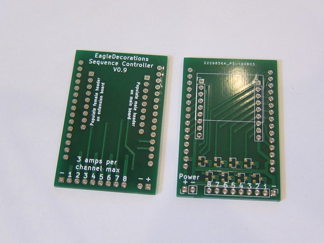
Boards are in the house!
JLCPCB did a nice job, and the boards look fine. Except:
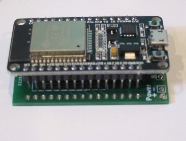
Yeah. Those pins are beautifully aligned a very precise 0.1” from where they are supposed to be…
Pro tip: Print out your design and put your components on it so that you can check the design.
Meta pro tip: Follow your pro tips.
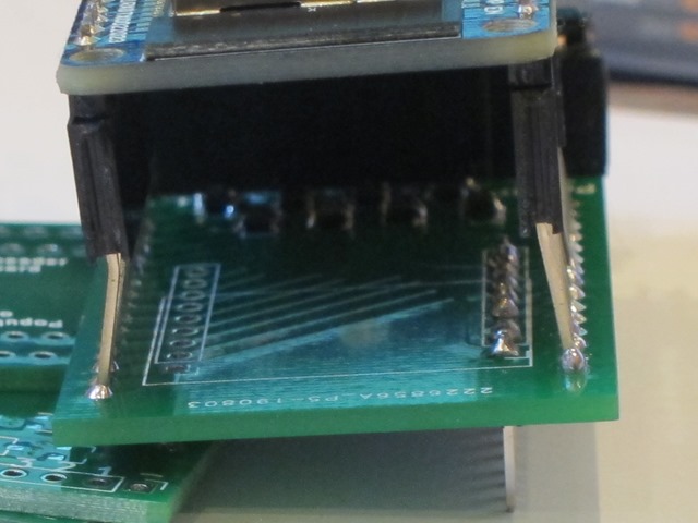
Anyway, that’s not the only problem; it turns out that the power and LED parts of the connector are right underneath the end of the board, so you can’t use a normal header on them (you could use a right-angle one if you wanted), so I did a new revision of the board with 1.0” rather than 1.1” for the ESP and extended the board so the connectors are out on the end. That’s on the slow ship from China right now.
Then I did a bit of bodging with some long-tail female headers so I could still do testing.
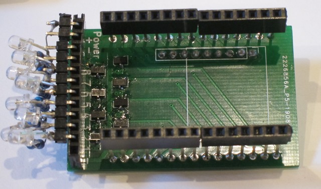
Then I put a header for the LEDs and carefully soldered 8 resistors and LEDs to the output pins, so that I have an 8-channel version available for writing software.
The MOSFETs are pretty darn small, but soldering them was mostly okay. I didn’t bother doing a stencil for this rev so I could reflow, but I will likely do that for the next version.
I have not yet tested what I think is the coolest part of the design; the board is both a main board and an expander board; you can connected a second version of the board on the back of the one with the ESP32 connected to it, and it will get you channels 9-16.
Here’s a quick video of the current state:
Sequence controller test from Eric Gunnerson on Vimeo.
It’s doing a “breathe” on all 8 LEDs with varying timespans for the delay action.
This is the 6th or 7th time that I’ve written sequencing software; there was a Motorola HC11 version, two AVR versions with AC dimming, a 4-channel chaser, and a couple of WS2812 versions.
They were all very simple; take the current state of all the output and drive the outputs to a new state over a given period of time. That works fine, but writing the animation can be annoying and it’s not very compact. This time I wanted to do something different and more elegant:
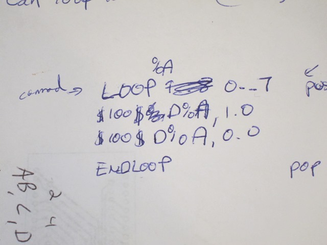
Here’s my spec:
That means ‘loop variable %A from 0 to 7’, and then execute a 100 cycle (1 second) dim of channel %A from its current state to 1.0 (full bright), and then do the same dim back down to zero.
I also wanted to write the vast majority of the code on my desktop, so I took a break and wrote three blog posts about how I do that. It’s basically compile-time dependency replacement with unit tests mostly written using TDD.
Then it was off to writing a *lot* of test code and a lot of classes; 18 difference source files, only two of which are ESP specific at this point. And 15 test classes to drive the tests. It mostly worked great, I did 95% of my coding and only had once latent bug that I had to track down on the ESP32. It was weird one that turned out to have very random behavior. I suspected it was uninitialized data, and that turned out to be mostly right; two subsequent calls to a method used the same stack and I forgot that strncpy doesn’t copy a null. But it all works now. Here’s the code the video is running:
$1$LOOP %B 100:10:-10
$1$LOOP %A 0:7
$%B$D%A,1.0
$%B$D%A,0.0
$1$ENDLOOP
$1$ENDLOOP”
Variable %B is used to change the cycle count for the operations from 100 to 10 in steps of 10, and then the inner loop cycles through the 8 different outputs. Everything works great.
The code all lives here if you want to see the actual code or a more realistic testing example.
Next steps:
- Wireless implementation to do the connection to the ESP
- Save and load of the animation
- Web interface to edit the animation.
- Change the language to move the cycle count into the “dim” command, as it’s not necessary for the loop commands.
- Build a second board to test channels 9-16.

So, what do you think ?