The snowflakes – five in total – have all been finished.
Well, mostly finished… there are three animating themselves on the gutters of the house right now, while the remaining two (which were on the house until this afternoon) are waiting for their waterproofing to cure.
This post will cover a lot of ground, since I missed a couple of updates along the way.
Assembly
When we last left our story, we had a PCB in the snowflake form and some laser-cut pieces of translucent acrylic that go on the front.
The next step was to put the LEDs on the board. My hope had been that I could use the hot air rework station to reflow all the LEDs, but a bit of experimentation showed that I was melting the LED cases and hand soldering was faster, so I went that way. I think a cheap reflow oven is in my future.
I used the following approach:
- Add solder to all the solder pads on the snowflake (55 * 4 = 220 of them).
- Carefully hold an LED in the right position, and touch two of the pads to tack it in place.
- Press down hard on that end of the LED, and touch each pad until the LED sinks down even with the level of the board at that end. .
- Repeat on the pads at the other end of the LED.
- Reheat the first two pads to get rid of the stresses induced when the second end was dropped down.
That was mostly straightforward, except it turns out that if you put the LEDs in backwards, they turn into HEDs – Heat Emitting Diodes – and you get to remove them and put new ones in their place. I put my new hot air rework station – a 9570W+ – to work at that.
Eventually, I got all of them soldered correctly, fixed some connection issues between the boards, and had something I could run my initial animation code on.
It worked.
My original plan was glue the PCBs directly to the acrylic, but I discovered that I liked the result better if there was some space between them. I did tests using pennies as spacers, grabbed my calipers to get some measurements and drew a quick drawing, and then came up with this in TinkerCad:
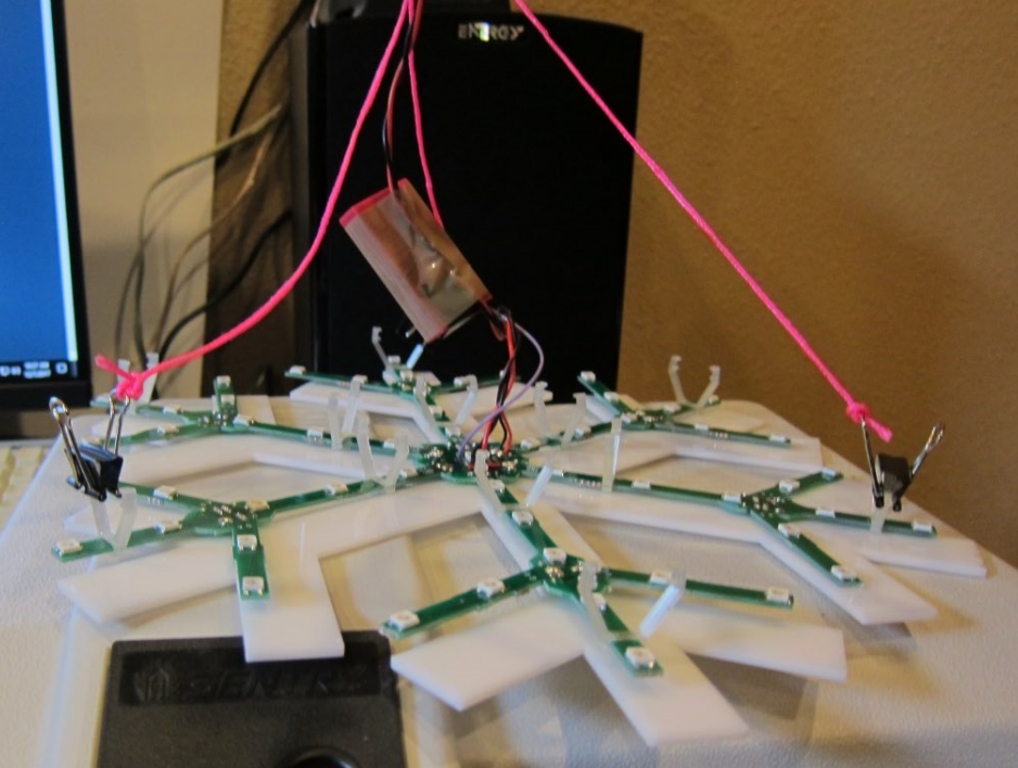
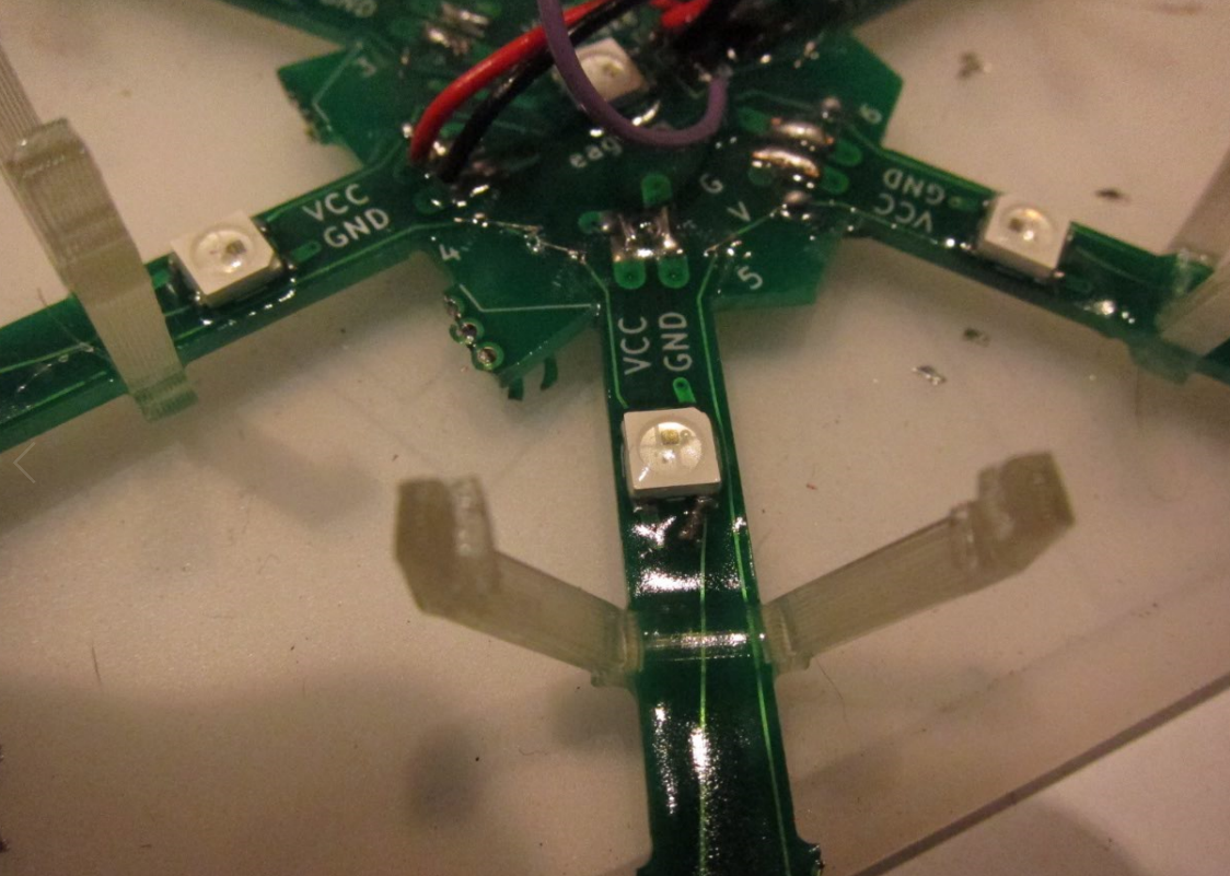
And then printed up a bunch of them in clear PLA. They mostly work pretty well; the only downside is that the connection at the small end needs to be flexible to warp around the board but that also makes it a bit weak, so I’ve broken a few of them. Carefully put them on the PC board and squeeze in the acrylic, and you end up with this:
Call this the first prototype. At this point, I was a bit tired of soldering and was waiting for some more parts to show up – and finding out that Amazon’s two-day prime shipping is only aspirational at times – so it was time to write some code.
Code
Both the code and the circuit designs live in GitHub here.
I’ve written four or five versions of color-blending animation code. Last year I wrote a nice abstraction that worked great for the linear strip animations I was doing, but it didn’t adapt very well to what I wanted to do here, so I went back to first principles.
Using polar coordinates, the code knows the location of each LED on the snowflake. For some of the animations, the color is determined by either the angle or distance of the LED from the center, and in these, there is just a simple mapping that says “add the animation offset to that number, and then use it to find a color”.
The nice part of this approach is that is gives me appropriate color blending across the whole snowflake.
I spend a few days on the code, and it’s decent as a first try. It implements four animations:
- A continuous rotation of all the colors around the arms of the snowflake.
- An animation of colors based on the distance of the LEDs from the middle.
- A “sparkle” effect; all the LEDs smoothly and slowly blend between colors, while random LEDs flash full white and then fade back to the current color. I wrote some nice code for this.
- A bouncing effect called “worm” that is a bit of a take on the Larson Scanner, but across opposite arms of the snowflake, also with color blending.
I had more ideas for animations, but decided to freeze the implementation so I could finish the build.
Autonomous display
For the prototype so far, I was driving it with a ESP that was powered by the serial port, and with a short ribbon cable carrying signals to the snowflake itself.
My plan was to put the ESP remote from the snowflake (so it could be under the eaves and shielded from rain), so I cut two-foot lengths of red/black/yellow wire (for power and signal), wired everything up, plugged it in…
And the LEDs started flashing randomly. Tried decoupling capacitors, tried signal resistors, tried a whole bunch of things, and nothing worked; if I made the signal line longer than about 10”, it wouldn’t work.
Trying to fix that consumed the better part of a day. Ultimately, I decided that the problem was that I was getting a lot of transients, so I decided to run the 5V power directly to the snowflake, and then chain the ESP off of that.
And it worked perfectly the first time, leading to this arrangement:
Plus 4 = 5
During the long hours of making four more of the PCBs – cursing my choice to use tiny pads for data connections and not doubling them – I realized that there was a far better way to do the attachment; if I allowed the boards to overlap vertically, I could use through-holes that aligned between the parts and just solder component leads into the holes. My guess is that I could do that basic board in about 1/10th the time, even less than that if I could reflow solder the LEDs. And the boards can probably be (mostly) square, which will make them easily fababble, easily broken apart, and they will fit tighter for better utilization.
Sounds like version 2 to me.
I didn’t take any pictures during this time, but it was a huge pain in the butt to get them all working; the tiny data paths were especially troublesome.
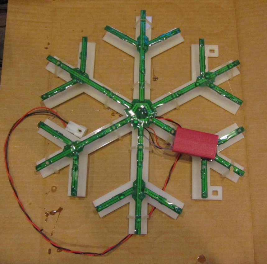
Finally that, was done, and I could turn to other matters. Four more Huzzahs were wired up:
and were all attached to the snowflakes.
With the Huzzah mounted close, it needed some protection, so a bit more time in TinkerCAD yielded a nice little case:
That’s a PrintrBot simple metal pro with a custom heated bed on it. I had the usual problem getting tolerances right, but eventually got to here:
Power
Whenever anybody asks me what the hardest part of these projects is, I always respond “cabling”.
LEDs are power hungry, and unfortunately small wires introduce voltage loss, which means you get color shift. If I had 3 snowflakes on one wire, the last one is going to be dimmer and the colors will likely shift as well. In my previous projects I’ve resorted to powering strips at both ends and using thick landscape lighting wire, but it’s a huge pain.
This time, I got smart.
WS2812s pull about 60 mA max if they are all white, and with 55 of them I needed 3.3 amps @ 5 volts. Since I can live without full white, I decided that 3 amps would be sufficient. And bought 5 of these:
One of these will be right next to each snowflake, and then I just need wires that supply something around 12 volts, and everybody will get a nice solid 5V supply and be happy. I reused the 10-gauge wire I had for the project this replaced, but I could easily get by with something like 18 gauge.
I’m not sure powering with DC is the right approach, however; it might be cheaper to go with small 5V AC power supplies and just use standard AC cords.
Waterproofing
I live in the Seattle area, and the holiday season is generally quite wet, and the electronics will need some protection from the elements.
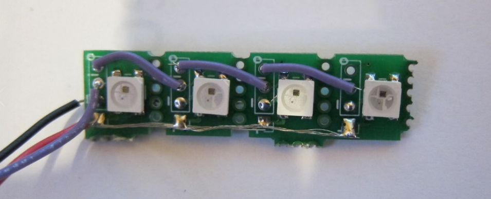
I have quite a bit of West Systems epoxy sitting in the garage leftover from a custom subwoofer enclosure I did a while back, but their website didn’t yield much information about its conductivity. So, I built this:
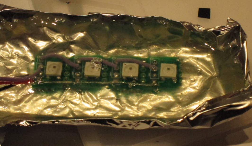
and embedded it in a whole lot of epoxy:
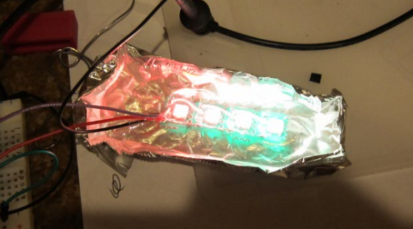
Works fine…
Distractions
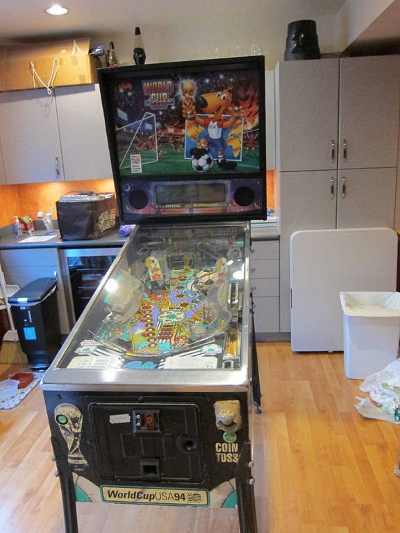
About this time, I had a couple of distractions. First off, this showed up from Italy:
Getting it picked up, legs on it, and ordering parts to recondition it took a bit of time.
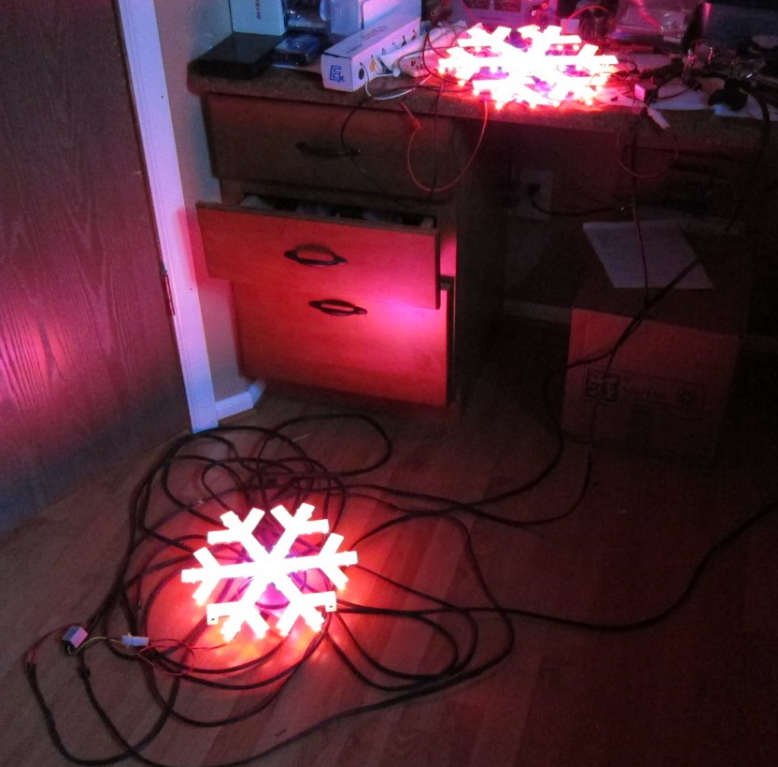
And, I had an event where I needed the snowflakes to be part of the display, so I totally finished two of the snowflakes and put them out on the house, trusting that the weather would stay unseasonably dry. Here’s the bench test:
You can see the DC->DC converter to the left of the lower snowflake.
I should at this point mention that pictures or video never do these colors justice; they are much more intense than they show up here.
Waterproofing part 2
To keep the attached wires in the right spots, the wires and the Huzzah needed to be supported above the PCB which will be covered in epoxy. Here’s what I ended up with:
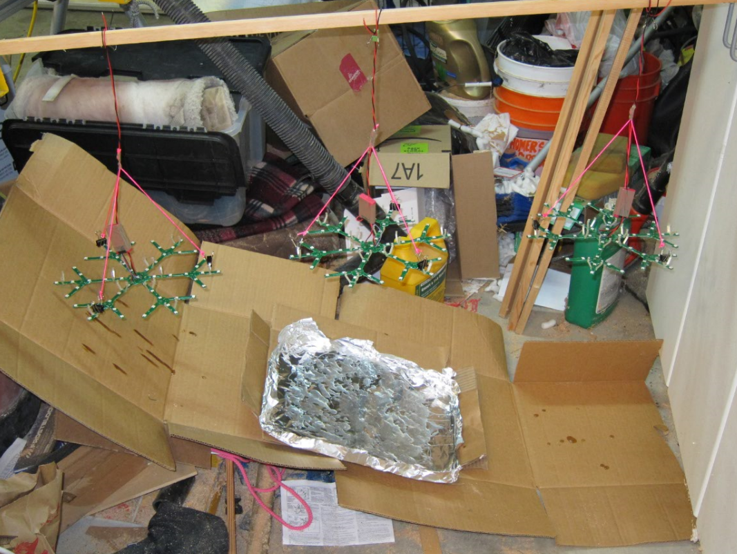
After I carefully poured epoxy over all the parts of the board that needed them, the boards got hung up to cure:
It being about 40 degrees in the garage, they did not cure overnight and eventually I had to pull them inside to finish curing. They looked like this when they finished curing:
I retested them. One of them worked perfectly, the other two did not; only some of the LEDs worked.
So, out came the air rework gun to debond the epoxy in an area and then I could trace from there. I ended up replacing about 5 LEDs; from what I can tell they were touching but no soldered, and the cold weather shrunk things enough so that the epoxy could get in there. I also had one pcb trace break (really?). Then, those two got an epoxy touchup to cover over the reworked areas. .
Finally, the huzzah box got hot-glued to the back and silicone was used to plug the hole.
Not perfect, but version 1.
You can also see the molex connectors that bring 5V into the snowflake.
Videos:
Snowflake from Eric Gunnerson on Vimeo.
Version 2
*Lots* of ideas for version two, which might be a commercial version.
- The whole mounting and waterproofing approach is far too finicky and may not work very well. I’m considering vacuum-forming the snowflake out of thinner plastic with both a front and back, and those can then be solvent welded (or siliconed) together to give me something that is truly waterproof. It will also give much better support for the PC boards.
- The approach of “click-together” pc boards worked, but it required fine-tuning for each and every joint and then detailed soldering for each part. And then rework when the stresses built up. Instead of click-together, I’m going to use overlapping boards that are connected with through-hole wiring. That will take me down to 10 easy-to-solder joints per arm, or about 60 in total. I also think I can get each of the PCs to be rectangular in format, and that will make panelization easier and waste less space. I think.
- I really need a way to reflow solder all the LEDs, and it may be time to make/buy a tiny reflow oven. Or *maybe* get somebody to do that for me, though the initial quotes I looked at are higher than I expected.
- Moving the ESP8266 onto the snowflake board, probably on the back. That would require adding a simple 3.3V regulator for power and (probably) programming pins. I’m currently using an ESP-12; I could probably get away with a simpler one but they are pretty cheap already so it may not be worth it.
- Add more built-in animations. Color wipes in the x/y direction, flash and off animations, concentric rotating color blends could all be done.
- WiFi coordination between standalone snowflakes, with a dedicated network just for the snowflakes, and *maybe* a separate gateway to connect to an existing wireless network.
- WiFi connection to an existing wireless network to allow control of the snowflakes. This might encompass setting their default set of animations, being able to download new animations, or being able to do “command control” over the wireless network, either just setting the animation that’s being run or driving every LED independently.


So, what do you think ?