After a bit of waiting, the boards showed up from OSHPark. they looked fine as far as I could tell.
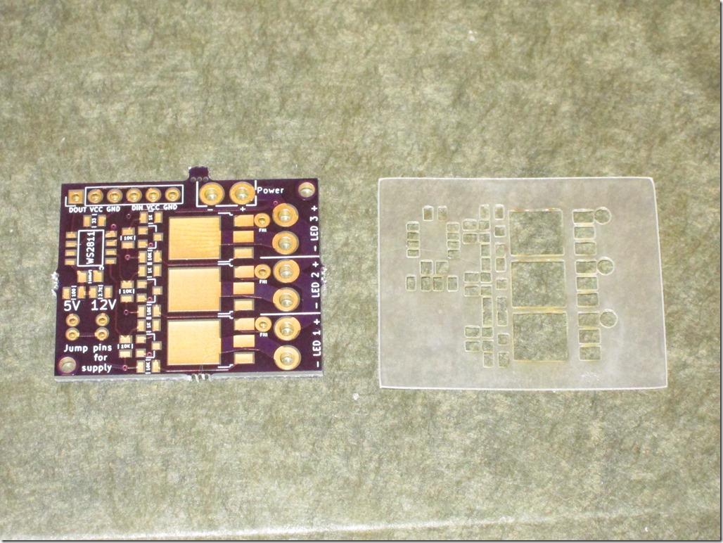
I had all the other parts to do a board, but I needed a paste stencil. I went into pcbnew, chose File->Export, and then chose to export the F.Mask (ie solder mask) layer to a SVG. I cleaned it up a bit to remove non-pad elements, went out to the laser cutter and cut a stencil out of 4 mil mylar:
Everything looked pretty good; there was good alignment between the board and the stencil. The spacing between the pads looked a little tight, but it’s a fairly fine pitched board, so it was mostly what I expected.
I carefully aligned the stencil and taped it on, got the solder paste out of the fridge, and applied it. Pulled up the stencil and it looked crappy, scraped it off, did it again, and got something that looked serviceable though there was more paste than I expected. Hmm.
Got out the components:
- 1 WS2811
- 1 33 ohm resistor
- 1 2.7k ohm resistor
- 6 10k ohm resistors
- 3 1k ohm resistors
- 3 NPN transistors
- 3 MOSFETS
- 1 100nF capacitor
and it took about 5 minutes to do the placement. Here’s the result:
I didn’t look at the picture at the time, but that’s a *lot* of solder paste.
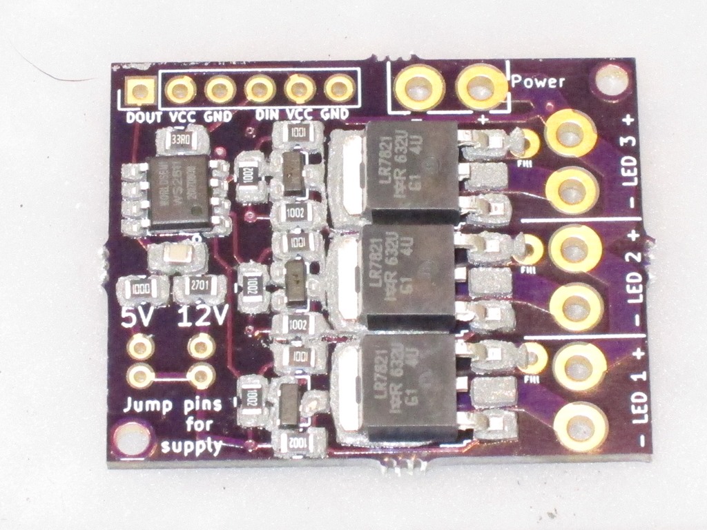
Into my reflow oven (Controleo 3 driving a B&D toaster oven), let it cycle, seemed fine, here’s the board:
Not my best work. Frankly, it’s a mess; there are obvious places where there is no solder, and obvious pins that are bridged together. I spent about 15 minutes with my VOM testing for continuity and there were 3 solder bridges and 7 unconnected section.
Something clearly went wrong. And I went back to PCBNew and it was *really* obvious.
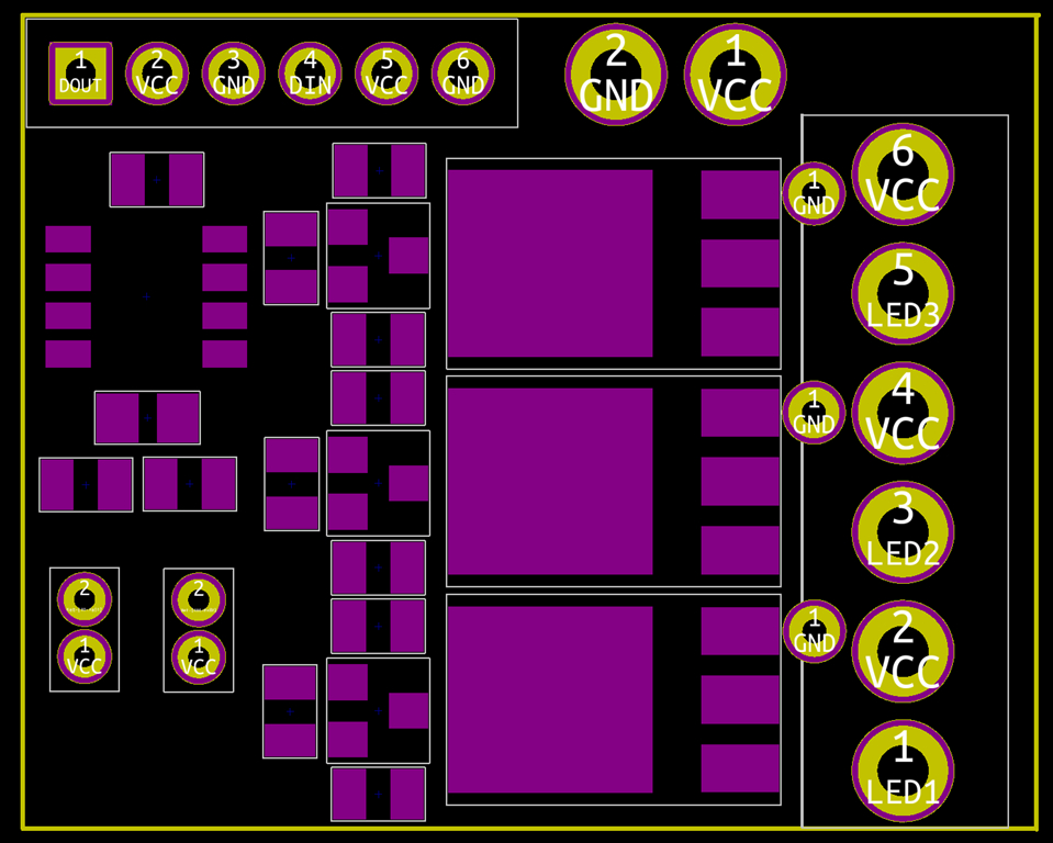
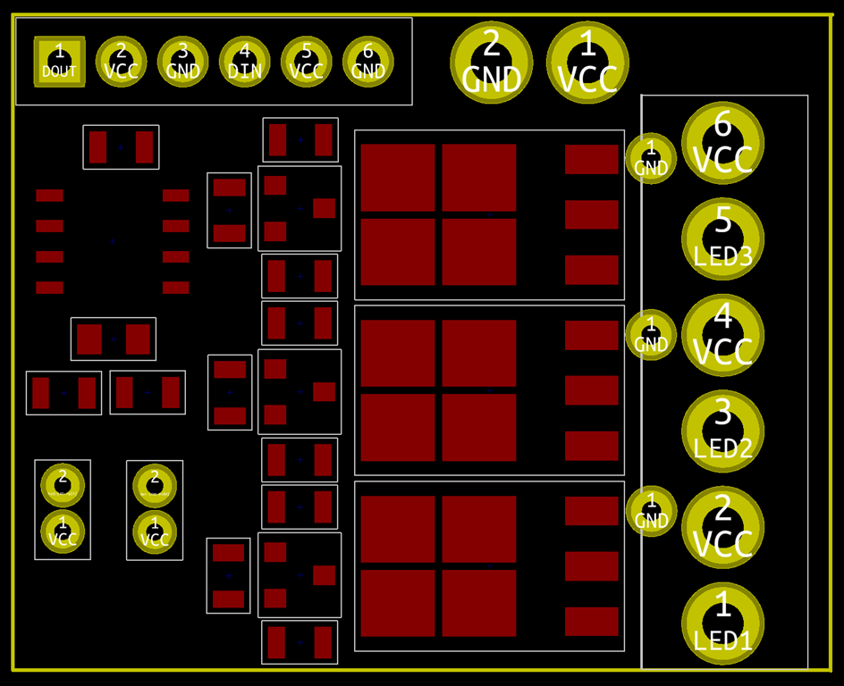
The layer you should choose for your stencil is F.Paste, not F.Mask. Here are the two next to each other (Mask left, Paste right):
The Mask layer sizes are positively giant compared to the paste ones. So, what happens if you use the Mask layer is that you have:
- A *lot* more paste on the board, especially the small pads which must have double the amount
- Solder paste with much reduced clearances.
What that means in reality is that when you put the components on, it squishes the solder paste together and connects pads that shouldn’t be connect. And then when you head it up, you either get bridges or one of the pads wins and sucks all the paste away from the other pad (how it wins isn’t clear, but it is clear that the huge MOSFET pads pulled all of the paste from the transistors next door).
This makes me feel stupid, but it is actually quite good news; it means that the design is fine and I just need to remake a stencil with the correct layer.
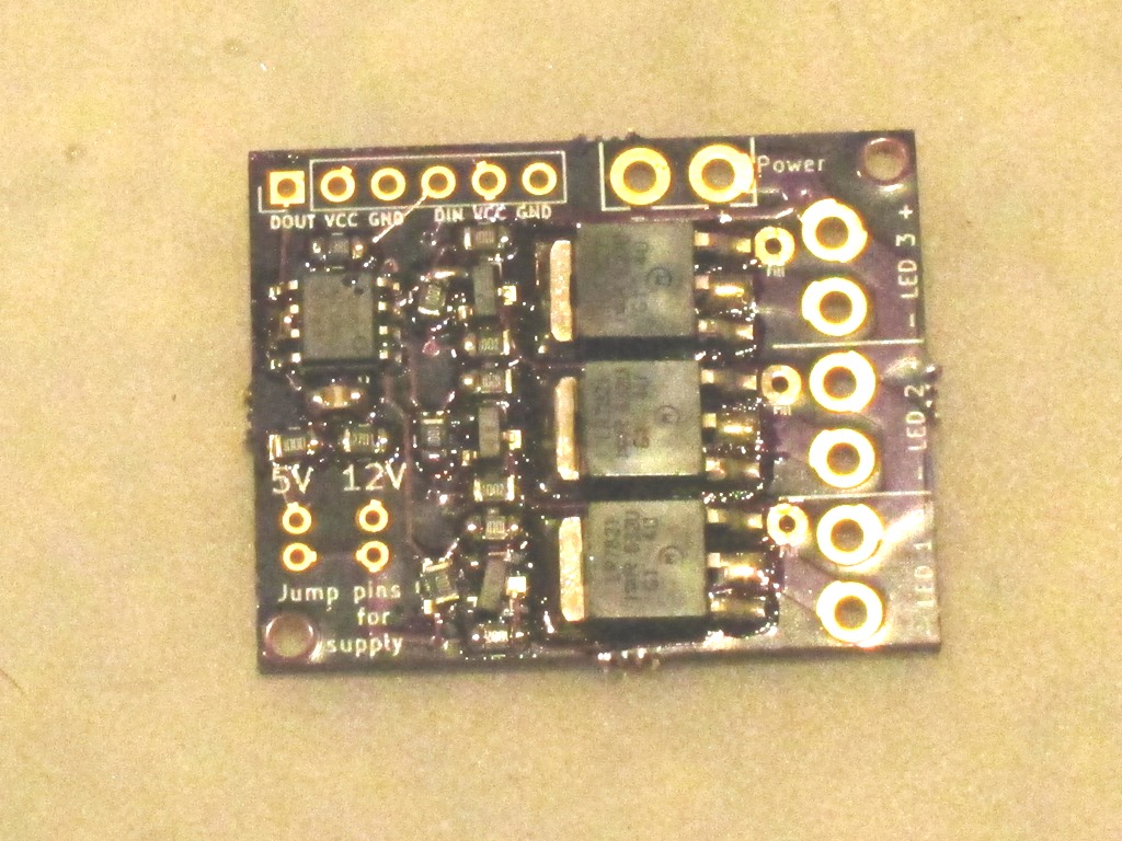
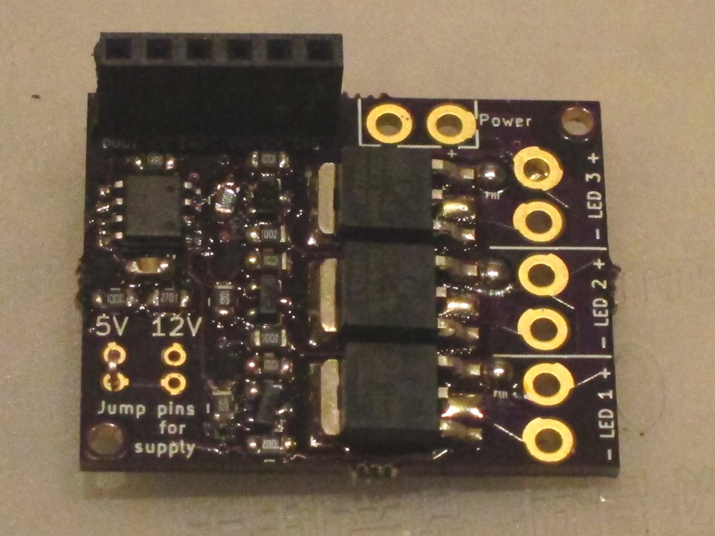
Anyway, after a lot more rework than I had expected, I ended up with this:
It’s still an ugly board, but does it work?
Well, I hooked up 5V, GND, and data in to one of my test rigs and a LED to the LED outputs.
And it works; the LED is on when I expect it to be on and off when I expect it to be off. All three outputs are fine.
The next test will be some testing to see how it fares with switching high current. And I’ll probably want to make another one using the correct stencil and hook it up for 12V operation to verify that.

So, what do you think ?